BoroSilicate Glass Products
Introduction
Typical Units/ Assemblies are multi-purpose units having flexibility of utility. These units have been standardised by incorporating all basic & essential features such as heating, stirring, condensation, fractionation, cooling etc. for multipurpose use. Therefore, though termed " Package Units" from constructional viewpoint they actually serve as "Flexi Units" from utility point of view. These units find use in educational institutions, R&D centres and industries. They can be conveniently and quickly modified according to specific process needs due to modular construction, Borosilicate glass offers additional benefits of universal corrosion resistance, visibility and cleanliness.
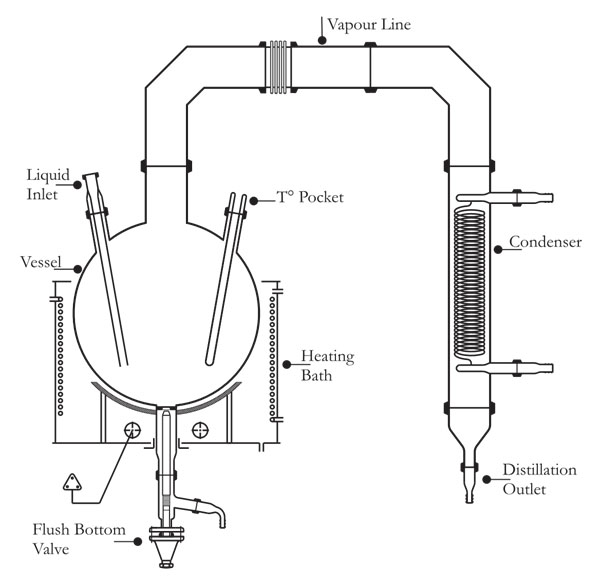
Simple Distillation Unit
It consists of a vessel mounted in a heating bath and fitted with a condenser for condensing the fumes. Receiver with drain valve can be added for receiving the condensate. The unit is available in vessel sizes of 20, 50, 100, 200 & 300 L and is suitable for operation under atmospheric pressure and full vacuum.
| Reactor Capacity | Bath KW | Vapour Line | CONDENSER HTA (m2) | Unit Cat. Ref. |
|---|---|---|---|---|
| 10 L | 2 | 50 DN | 0.2 | SDU 10 |
| 20 L | 3.6 | 80 DN | 0.35 | SDU 20 |
| 50 L | 4.5 | 100 DN | 0.5 | SDU 50 |
| 100 L | 6 | 150 DN | 1.5 | SDU 100 |
| 200 L | 8 | 150 DN | 1.5 | SDU 200 |
| 300 L | 12 | 225 DN | 2.5 | SDU 300 |
* This units is also available in cylindrical vessel.
* Heating Mantel is also available in the same unit, please specify before the order.
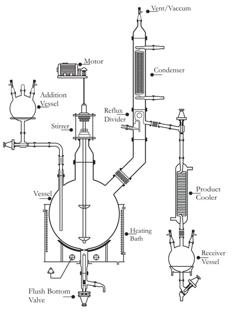
Reaction Distillation Unit
This unit is used for carrying out reactions under stirred condition and with provision for simple reflux distillation.
The reaction vessel is mounted in a heating bath and fitted with addition vessel, motor-driven stirrer and provision for condensation with refluxing.
The product is sub-cooled and collected in a receiver.
The units is available in vessel sizes of 20, 50, 100 & 200L, 300L and is suitable for operation under atmospheric pressure and full vaccum.
| Reactor Bath Capacity | Bath KW | Addition Vessel Size | Vapour Line | CONDENSER HTA (m2) | RO.COOLER HTA (m2) | Unit Cat. Ref. | Unit Cat. Ref. |
|---|---|---|---|---|---|---|---|
| 10 L | 2 | 2 L | 50 DN | 0.2 | 0.1 | 2 L | RDU 10 |
| 20 L | 3.6 | 5 L | 80 DN | 0.35 | 0.1 | 5 L | RDU 20 |
| 50 L | 4.5 | 5 L | 100 DN | 0.5 | 0.2 | 5 L | RDU 50 |
| 100 L | 6 | 10 L | 150 DN | 1.5 | 0.35 | 10 L | RDU 100 |
| 200 L | 8 | 20 L | 150 DN | 1.5 | 0.35 | 20 L | RDU 200 |
| 300 L | 12 | 20 L | 225 DN | 2.5 | 0.5 | 20 L | RDU 300 |
* This unit is also available in cylindrical vessel .
* Heating Mantel is also available in the same unit , please specify before the order.
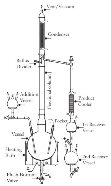
Fraction Distillation Unit
This is essentially a compact batch-type fractional distillation unit in which the reboiler consists of a vessel mounted in a heating bath and with a packed column above. The vapours from top are condensed and can be refluxed as per requirement.
The top product is sub-cooled and collected in receivers.The bottom product is finally drained from the reboiler through a drain valve.
The unit is available in vessel sizes of 20,50,100 & 200L,300L and is suitable for operation under atmospheric pressure and full vaccum.
| Reactor Bath Capacity | Bath KW | Addition Vessel Size | Vapour Line | CONDENSER HTA (m2) | RO.COOLER HTA (m2) | Unit Cat. Ref. | Unit Cat. Ref. |
|---|---|---|---|---|---|---|---|
| 10 L | 2 | 2 L | 50 DN | 0.2 | 0.1 | 2 L, 2 L | FDU 10 |
| 20 L | 3.6 | 5 L | 80 DN | 0.35 | 0.1 | 5 L, 5 L | FDU 20 |
| 50 L | 4.5 | 5 L | 100 DN | 0.5 | 0.2 | 5 L, 5 L | FDU 50 |
| 100 L | 6 | 10 L | 150 DN | 1.5 | 0.35 | 10 L, 10 L | FDU 100 |
| 200 L | 8 | 20 L | 150 DN | 1.5 | 0.35 | 20 L, 20 L | FDU 200 |
| 300 L | 12 | 20 L | 225 DN | 2.5 | 0.5 | 20 L, 20 L | FDU 300 |
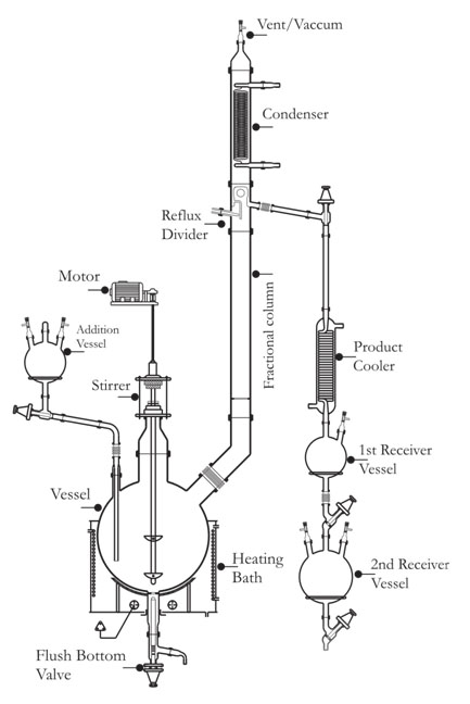
Reflux Reaction Cum Distillation Unit
This is a versatile unit and can be used as Reaction Distillation Unit, Fractional Distillation Unit or a combination of both. All features of Reaction Distillation Unit and Fractional Distillation Unit are incorporated.
The units is available in vessel sizes of 20, 50, 100 & 200L, 300L and is suitable for operation under atmospheric pressure and full vaccum.
| Reactor Bath Capacity | Bath KW | Addition Vessel Size | Vapour Line | CONDENSER HTA (m2) | RO.COOLER HTA (m2) | Unit Cat. Ref. | Unit Cat. Ref. |
|---|---|---|---|---|---|---|---|
| 10 L | 2 | 2 L | 50 DN | 0.2 | 0.1 | 2 L, 2 L | RDU 10 |
| 20 L | 3.6 | 5 L | 80 DN | 0.35 | 0.1 | 5 L, 5 L | RDU 20 |
| 50 L | 4.5 | 5 L | 100 DN | 0.5 | 0.2 | 5 L, 5 L | RDU 50 |
| 100 L | 6 | 10 L | 150 DN | 1.5 | 0.35 | 10 L, 10 L | RDU 100 |
| 200 L | 8 | 20 L | 150 DN | 1.5 | 0.35 | 20 L, 20 L | RDU 200 |
| 300 L | 12 | 20 L | 225 DN | 2.5 | 0.5 | 20 L, 20 L | RDU 300 |
* These unit is also available in cylindrical vessel .
* Heating Mantel is also available in the same unit , please specify before the order.
Multi - Purpose R&d Unit
This unit is more versatile and cost effective, capable of working at atmospheric pressure or under full vacuum .
This unit is suitable of performing the boiling under reflux, stripping and continuous distillation, batch distillation, Interface separation, without chemical reaction. The unit can be modified as per the specification and requirement of the customer.
| Reactor Bath Capacity | Bath KW | Addition Vessel Size | Vapour Line | CONDENSER HTA (m2) | RO.COOLER HTA (m2) | Unit Cat. Ref. | Unit Cat. Ref. |
|---|---|---|---|---|---|---|---|
| 10 L | 2 | 2 L | 50 DN | 0.2 | 0.1 | 2 L, 2 L | MRD 10 |
| 20 L | 3.6 | 5 L | 80 DN | 0.35 | 0.1 | 5 L, 5 L | MRD 20 |
| 50 L | 4.5 | 5 L | 100 DN | 0.5 | 0.2 | 5 L, 5 L | MRD 50 |
| 100 L | 6 | 10 L | 150 DN | 1.5 | 0.35 | 10 L, 10 L | MRD 100 |
* These unit is also available in cylindrical vessel .
* Heating Mantel is also available in the same unit , please specify before the order.
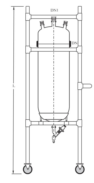
Mobile Vessel
Mobile Vessel is perfect for pilot plant and production use to transport and store products. Cylindrical mobile vessel can be supplied from 30 to 200 liter and spherical vessels from 50 to 200 liter. If required, it can also be graduated.
| NOMINAL CAPACITY LTR | DN | DN 1 | L | CONDENSER HTA (m2) | CAT. REF. with PUMP |
|---|---|---|---|---|---|
| 30 | 300 | 40 | 1500 | MCV30 | MCV30/P |
| 50 | 300 | 40 | 1700 | MCV50 | MCV50/P |
| 100 | 450 | 50 | 1950 | MCV100 | MCV100/P |
| 150 | 450 | 50 | 2250 | MCV150 | MCV150/P |
| 200 | 450 | 50 | 2550 | MCV200 | MCV200/P |
NOTE : "L" is Vary ±50mm or as require size in special case. Mobile Vessel is also available in Spherical vessel .
Jacketed Cylindrical Mixing Reactor
| Reactor Capacity | Jacketed Mixing Reactor Cat. Ref. |
|---|---|
| 5 L | JMR 5 |
| 10 L | JMR 10 |
| 20 L | JMR 20 |
| 30 L | JMR 30 |
| 50 L | JMR 50 |
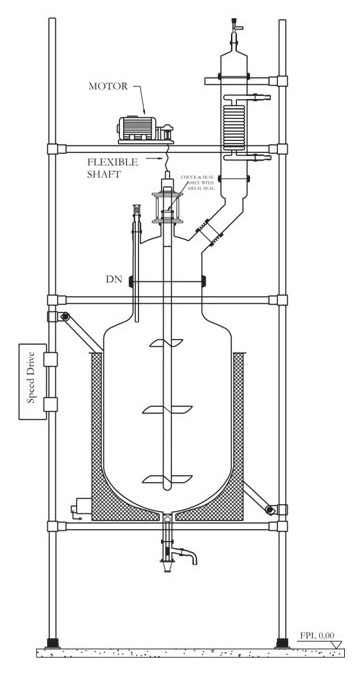
Mixing Reactor
Mixing reactor systems represent a long-term evaluation of equipment and customer requirements. The mixing reactors are preferably used for wide applications in laboratory, pilot plant & for small-scale production. They reduce the need for investment in permanent installations & also reduce the pressure & temperature losses resulting from pipeline installations. These reactors are available with spherical shape & cylindrical shape. These reactors are also available in cylindrical jacketed form.
Construction of assembly :
SPHERICAL & CYLINDRICAL Mixing Reactor
| Reactor Capacity | SPHERICAL CAT. REF. | Cylindrical Cat. Ref. |
|---|---|---|
| 20 L | SMR 20 | CMR 20 |
| 50 L | SMR 50 | CMR 50 |
| 100 L | SMR 100 | CMR 100 |
| 200 L | SMR 200 | CMR 200 |
| 300 L | SMR 300 | CMR 300 |
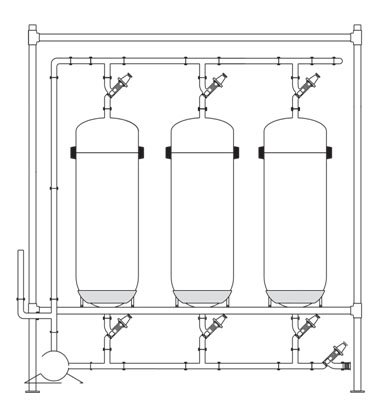
STORAGE TANK OF VOLUME 100–500
They are composed of glass cylindrical kettles or flasks of capacity200-500, discharges of vessels are consistent by glass piping DN 50/40.
Cylindrical Vessel
| NOMINAL CAPACITY LTR | D MM |
L MM | CAT. REF. |
|---|---|---|---|
| 100 L | 470 | 1020 | SCY100 |
| 150 L | 470 | 1315 | SCY150 |
| 200 L | 600 | 1190 | SCY200 |
| 300 L | 600 | 1590 | SCY300 |
| 400 L | 600 | 1715 | SCY400 |
| 500 L | 760 | 1550 | SCY500 |
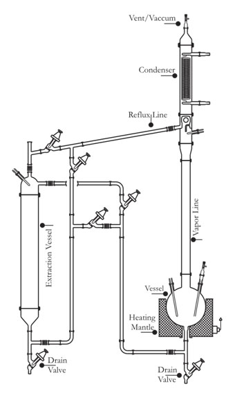
Liquid-liquid Extraction Unit
Liquid extraction, sometimes called solvent extraction, is the separation of constituents of a liquid solution by contact with another insoluble liquid. The unit described here is for a semi-batch operation.
The liquid to be extracted is poured into an extraction vessel. Solvent is boiled in a reboiler vessel and condensed in an overhead condenser, the condensed liquid collected in a reflux divider and passed through pipework to the extraction vessel. The pipework incorporates valves in order that the solvent can enter the extraction vessel at either the base of the top, depending on the relative densities of the solvent and liquid to be extracted. The solvent and the extracted liquid pass back to the reboiler and the process is repeated until the extraction is complete. The extraction vessel is then drained and the solvent evaporated from the reboiler vessel and collected in the extraction vessel enables the two liquids to be drained form their respective vessels.
The unit is available in vessel sizes of 10, 20, & 50L and is suitable for operation under atmoshepric pressure.
| REACTOR CAPACITY | BATH KW | VAPOUR LINE | EXTRACTION VESSEL | CONDENSER M2 | UNIT CAT. REF. |
|---|---|---|---|---|---|
| 10 L | 3 | 40mmx1m | 10 L | 0.35 | LLU 10 |
| 20 L | 4.5 | 50mmx1m | 20 L | 0.5 | LLU 20 |
| 50 L | 6 | 80mmx1m | 50 L | 1.5 | LLU 50 |
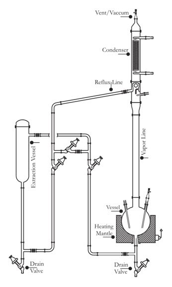
Solid Liquid Extraction Unit
This operation involves preferential solublising of one or more soluble constituents (solutes) of a solid mixture by a liquid solvent. The unit described here is for a semi-batch operation.
The solid to be extracted is put inside a glass fiber bag and placed in an extraction vessel. Solvent from the reboiler is continuously evaporated,condensed and circulated through a reflux divider by means of piping network and valves. When desired/ steady concentration of solute is achieved in the solution the operation is discontinued. The solution is drained off and collected for further use.
After charging fresh solid in fiber bag and solvent in reboiler, the cycle can be restarted again.The unit is available in vessel sizes of 10, 20, & 50L and is suitable for operation under atmospheric pressure.
| REACTOR CAPACITY | BATH KW | VAPOUR LINE | EXTRACTION VESSEL | CONDENSER M2 | UNIT CAT. REF. |
|---|---|---|---|---|---|
| 10 L | 3 | 40mmx1m | 10 L | 0.35 | SLU 10 |
| 20 L | 4.5 | 50mmx1m | 20 L | 0.5 | SLU 20 |
| 50 L | 6 | 80mmx1m | 50 L | 1.5 | SLU 50 |
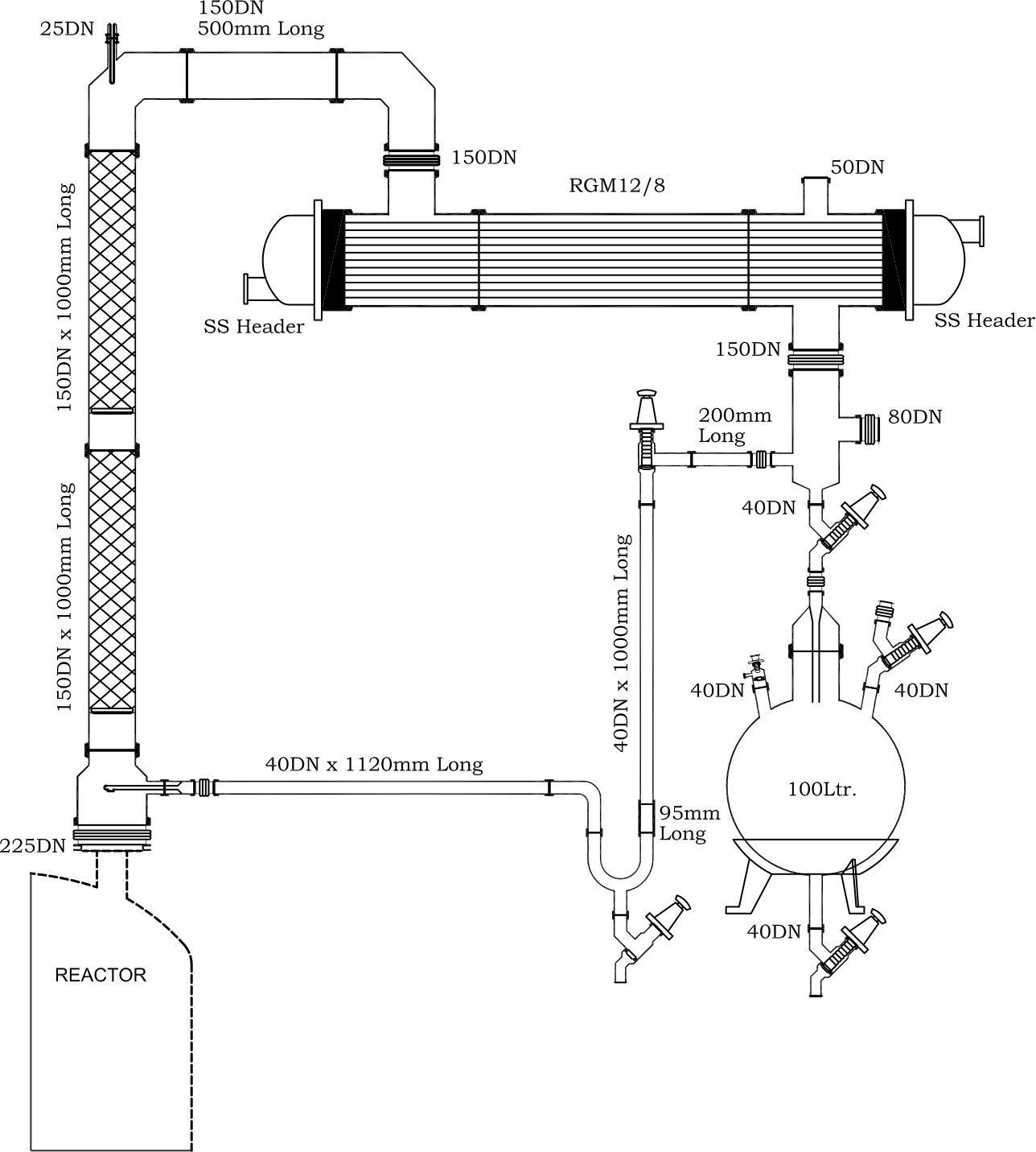
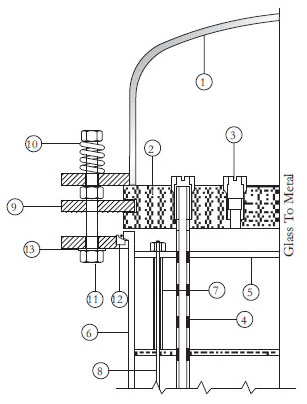
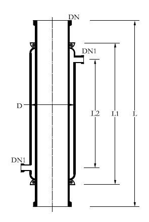
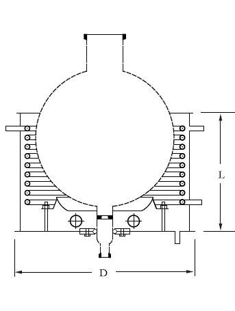
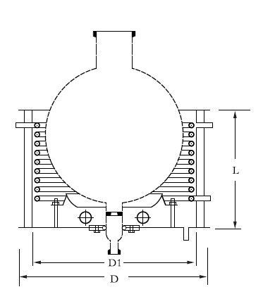
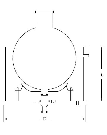
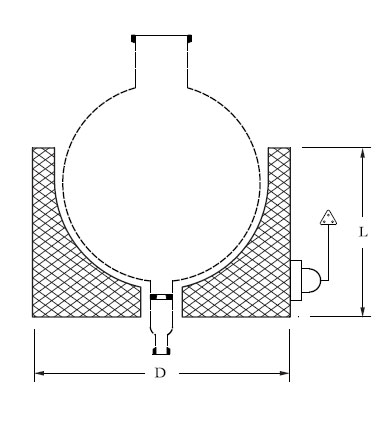
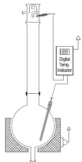
Assemblies Over Glass Lined Reactor
Glass Lined Reactors are used instead of glass reactors specially when scale of operation is large and relatively high pressure steam is to be used as heating media. Quite often assemblies like Simple Distillation Unit, Reaction Distillation Unit, Fractional Distillation Unit etc. are installed above glass lined reactors. The basic features of these assemblies remain the same but glass shell and tube heat exchanger is preferred due to large scale of operation. A typical fractional distillation unittype assembly over GLR is shown in nearby figure. The assemby can be separated into different categories.
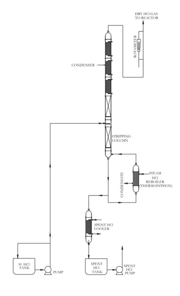
Hcl gas Generation - Azeotropic Boiling Route
Commercial hydrochloric acid is available in the market as 30% aqueous solution and is widely used in industry in large quantities. But for certain applications e.g. in bulk drug/pharmaceutical industry HCl gas is required in gaseous form. Such users generate anhydrous HCl from commercial grade for their captive consumption. Several methods have been adopted and generation through BOILING ROUTE is also a reliable technique. Salient features :
RAW MATERIAL & UTILITY REQUIREMENTS. :
The indicative requirements for 20kg/hr HCl gas generator are given below:
HCI Gas Generator
(Sulphuric Acid Route).
Commercial hydrochloric acid is available in the market as 30% aqueous solution and is widely used in industry in large quantities. But for certain applications e.g. in bulk drug/pharmaceutical industry HCI gas is required in anhydrous state for critical reactions where moisture cannot be tolerated. Such users generate anhydrous HCI from commercial grade for their captive consumption. Several methods have been adopted but generation through SULPHURIC ACID ROUTE is the most reliable and handy technique.
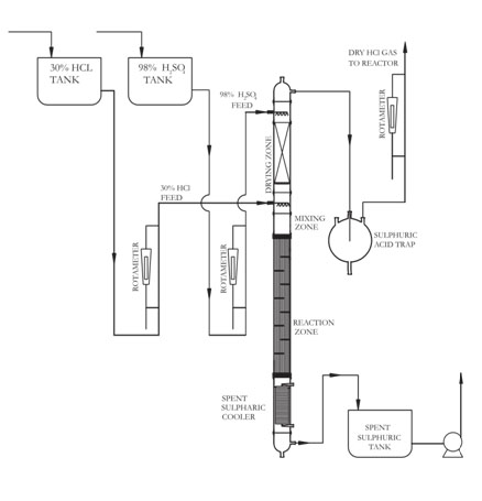
Salient Features :
Raw Material Requirement
The indicative requirements for 20 kg/hr HCI gas generator are given below:
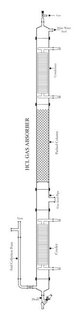
Hcl GAS ABSORBER - ADIABATIC TYPE
HCL absorption columns are used for absorption of Hydrochloric gas which statutorily are not permitted to vent into the atmosphere, and to produce the HCl acid. Hydrogen Chloride is very soluble in water but it's absorption is complicated by the high heat of solution and the high partial pressure over warm concentrated solutions. In practice, the basic problem in making concentrated solutions is one of efficient heat removal. In this type of absorber, the heat of absorption is removed by evaporation of water and acid in the column. The vapour being condensed is diluted with 'makeup' therefore, mostly removed via condenser. Concentration and cooling of the liquid phase is assisted by evaporation of water to maintain the vapour/liquid equilibrium in the lower part of the packed section. The column is constructed with a series of packed sections, a gas introduction point below that, a condenser on the top, and a cooler at the bottom and water is sprayed from the top and acid is collected from the bottom. Hcl absorption columns are available in 80DN to 300DN diameter (for the gas rate 10 Kgs/hr to 300 Kgs/hr approx.)
| PACKED COLUMN | CONDENSER HTA (m2) | GAS RATE (Approx.) | EXTRACTION VESSEL | CAT. REF. |
|---|---|---|---|---|
| 80mmx3m | 0.35m2x2 | 40mmx1m | 10 Kg/hr | HCL3 |
| 100mmx4m | 0.5m2x2 | 50mmx1m | 20 Kg/hr | HCL4 |
| 150mmx4m | 1.5m2x2 | 80mmx1m | 60 Kg/hr | HCL6 |
| 225mmx4.5m | 2.5m2x2 | 80mmx1m | 150 Kg/hr | HCL9 |
| 300mmx4.5m | 2.5m2x2 | 80mmx1m | 300 Kg/hr | HCL12 |
GAS ABSORBER - FALLING FILM TYPE
Process Description
Efficient gas absorption depends on the following: 1. Intimate contact 2. Efficient Heat Transfer This is achieved in a Falling Film Absorber which is essentially a shell & tube heat exchanger in which both, gas to be absorbed and absorbing liquid, flows co-currently downward with extraction of heat by circulation of coolant in the shell. The abssorbing liquid is circulated through a tank till desired concentration is achieved. The liquid flows at such a rate that the tubes do not flow full of the liquid but instead, descends by gravity along the inner walls of the tubes as a thin film. Obviously, this produces a much greater linear velocity for a given rate flow than could be obtained if the tube flowed full. The equipment works as a number of water cooled-wall columns in parallel and each tube is provided with distribution system on top to effect uniform distribution of both liquid and gas and also formation of a thin liquid film on the inner surface of the tube.
SALIENT FEATURES
Other Area Of Application:
SPECIFICATIONS:
| NOMINAL SIZE (mm) | ABSORBER AREA (m2) | NO. OF TUBE TUBE OD (mm) | MAX. GAS ABSORPTION RATE ( Pure HCL) ( kg/Hr) | MAX. ACID PROD. RATE (As 30% CL )(kg/Hr) |
MAX. ACID PROD. RATE (As 30% CL )(kg/Hr) |
|---|---|---|---|---|---|
| 80 | 1.00 | 4/20 | 30 | 100 | FFA3 |
| 100 | 1.76 | 7/20 | 60 | 200 | FFA4 |
| 150 | 4.80 | 19/20 | 150 | 500 | FFA6 |
| 225 | 7.80 | 31/20 | 250 | 833 | FFA9 |
| 300 | 15.30 | 61/20 | 500 | 1667 | FFA12 |
| 400 | 36.00 | 143/20 | 1175 | 3917 | FFA16 |
| 450 | 47.00 | 187/20 | 1500 | 5000 | FFA18 |
| 600 | 84.00 | 333/20 | 2700 | 9000 | FFA24 |
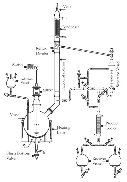
BROMINE RECOVERY PLANT
Process Description
The feed is acidified with 30% HCl acid and acidified feed is fed to the scrubber by pump to scrub uncondensed chlorine from vent condenser and return back to the reaction column. In some cases the part feed is preheated using effluent from the reaction column prior to the entry of reaction column and part feed is fed to the scrubber to conserve energy.
Chlorine and Steam are also fed to the reaction column.
In the reaction column the feed is reacted with chlorine gas & bromine is liberated instantly. This liberated bromine is stripped out of the solution by live steam. The bromine and water vapor stream leaves the top of the column and enters the condenser . Condensate falls into the Phase Separator where it forms two phases, the light aqueous phase (water) being returned to the column ,while the heavy phase(Bromine) being feed the purification column. Cooling Water & Chilled Water is used as cooling media in heat exchanger provided at the top of the column to condense water vapor& Bromine.
Purification of the Bromine is achieved by distillation. Heat being introduced into the column through the reboiler. Bromine and Chlorine vapor leave the top of the column and enter the condenser .The Bromine gets condensed in the condenser and falls back into the column while uncondensed Chlorine vapor along with traces of Bromine escapes from the condenser and enter into the vent condenser, where remaining Bromine gets condensed and back to the crude Bromine receiver.
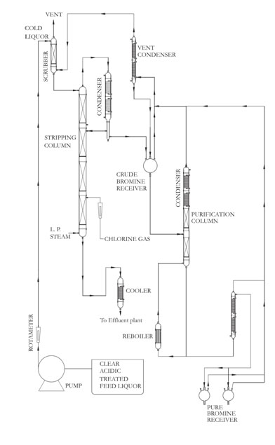
Pure Bromine is cooled in a product cooler to and goes to product receiver. Guard condenser is also provided at the top of the receiver to prevent escape of Bromine. Bromine is then collected in glass bottles. From Industrial Effluents (NaBr/KBr/HBr) From Sea -Bittern . Available up to 600 mm Dia. Over view of the system The system consists of :
Raw Material Requirement :
Products Specifications
Bromine Liquid : 99.7% (w/w, min)Chlorine : 0.3 % (w/w, max)
Non -volatile matter : Balance
SULPHURIC ACID DILUTION PLANT
Process Description
The unit consists of a Dilution Chamber, followed by a Heat Exchanger. Dilution Chamber is used for diluting concentrated Sulphuric acid to the desired concentration and the Heat Exchanger is used for bringing down the temperature of dilute acid to desired temperature, (when the concentrated acid mixes with water, large amounts of heat are released). The Heat Exchanger is of Shell and Tube type to dilute the acid. The acid should be added slowly to cold water to limit the buildup of heat. If water is added to the concentrated acid, enough heat can be released at once to boil the water and separate the acid. Sulfuric acid reacts with water to form hydrates with distinct properties.
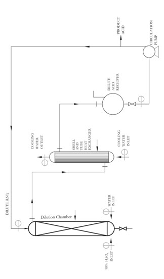
The system consists of:
Outstanding Features
Heat Exchangers
There are two types of glass heat exchangers, coli type and shell and tube type.
Coil Type Heat Exchanger
Coil type heat exchanger is mainly used as condenser or cooler. It can, however, be used for heat transfer between liquids & gases in general. It has the coil battery welded to the jacket making a one Piece unit. The maximum allowable pressure in the coils is 2.7 bar gauge.
Performance Data
An approximate calculation of heat transfer surface areas can be based on the following
guide figure for heat transfer coefficients.
The figures do not show the maximum performance of the units but are a general indication
of typical working conditions.
| Jacket side Medium | Vapour to be condensed | Liquid | Gas |
|---|---|---|---|
| Coil side medium | Cooling water | Cooling water | Cooling water |
| Heat transf. coeff. Kcal/hr – m2 – 0c |
200-250 | 100-150 | 40-60 |
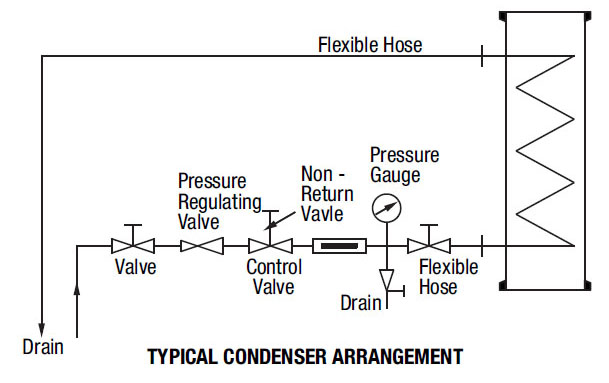
Precautions to use condenser are as follows:
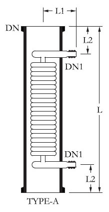
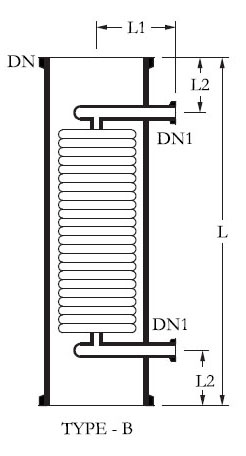
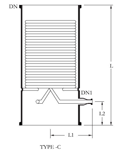
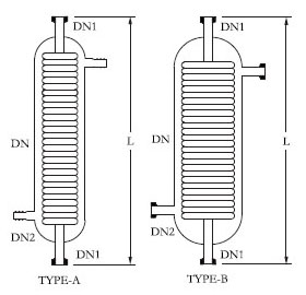
Glass Condenser
| HTA (m2) | DN | D / DN1 mm | L | L1 | L2 | Type | Jacket Cap. Ltr. | Coolant Rate Kg/h | *FCSA SHELL (cm2) | CAT. REF. |
|---|---|---|---|---|---|---|---|---|---|---|
| 0.20 | 40 | 16 | 600 | 85 | 100 | A | 1 | 750 | 4.5 | HE1.5/2 |
| 0.35 | 50 | 16 | 600 | 90 | 100 | A | 1.25 | 1300 | 5 | HE2/3.5 |
| 0.35 | 80 | 16 | 600 | 90 | 100 | A | 2 | 1300 | 5 | HE3/3.5 |
| 0.50 | 100 | 19 | 600 | 120 | 100 | A | 4 | 2400 | 30 | HE4/5 |
| 0.60 | 100 | 19 | 750 | 120 | 100 | A | 6 | 2400 | 30 | HE4/6 |
| 1.00 | 150 | 25 | 600 | 150 | 100 | B | 9 | 2600 | 52 | HE6/10 |
| 1.50 | 150 | 25 | 850 | 150 | 125 | B | 11 | 2600 | 52 | HE6/15 |
| 2.50 | 225 | 25 | 800 | 180 | 125 | B | 18 | 3300 | 142 | HE9/25 |
| 2.50 | 300 | 25 | 600 | 250 | 125 | B | 25 | 5700 | 175 | HE12/25 |
| 4.00 | 300 | 25 | 900 | 250 | 125 | B | 35 | 5700 | 175 | HE12/40 |
| 4.00 | 400 | 25 | 600 | 265 | 125 | B | 60 | 6200 | 450 | HE16/40 |
| 4.00 | 400 | 25 | 600 | 265 | 125 | B | 60 | 6200 | 450 | HE16/40 |
| 6.00 | 450 | 40 | 750 | 325 | 150 | B / C | 100 | 4800 | 820 | HE18/60 |
| 8.00 | 450 | 40 | 900 | 325 | 150 | B / C | 110 | 6200 | 820 | HE18/80 |
Note : L / L1 / L2 may be + 10mm.
* FCSA- Free Cross Section Area .
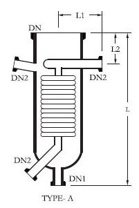
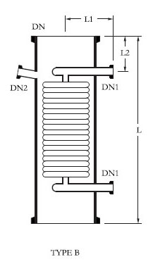
Glass Boiler
Type HEB4, HEB6 and HEB9 glass coil-type boiler is normally mounted in external
circulatory loops using a spherical vessel as the main still. It should not be installed in the
bottom of a flask or column.
The other types of glass coil-type boiler detailed on this page is again mounted in circulatory
loops but as it’s nominal bore is same at the top and bottom, this unit can under certain
circumstances, be installed one above the other to achieve multiples of the basic heat
transfer area.
The maximum pressure in the coils is 3.0 barg. The maximum differential pressure across the
coils is 3.0 bars. Please refer to the performance data for glass coil-type.
Performance Data
The maximum permissible steam pressure at the coil inlets of boilers is 3.0 bar.g. which is
equivalent to a temperature of about 143oC with saturated steam. Higher temperatures can
be achieved by using heat transfer fluids.
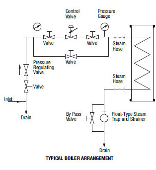
The heat transferred in most sizes can be considered on average as 250 Kcal/hr – m2 0c with a steam pressure in the coils of 3.0 barg, although this figure declines marginally at lower pressure.
PRECAUTIONS TO USE GLASS BOILER ARE AS FOLLOWS:
| HTA (m2) | DN | DN1 | DN2 | L | L1 | L2 | *FCSA SHELL (cm2) | Jacket Cap. Ltr. | Type | CAT. REF. |
|---|---|---|---|---|---|---|---|---|---|---|
| 0.15 | 100 | 25 | 25 | 375 | 125 | 100 | 40 | 2 | A | HEB 4 |
| 0.15 | 100 | 25 | - | 400 | 125 | 100 | 40 | 3 | B | HEB 4/4 |
| 0.35 | 150 | 40 | 25 | 450 | 150 | 100 | 50 | 5 | A | HEB 6 |
| 0.35 | 150 | 25 | - | 500 | 150 | 100 | 50 | 7 | B | HEB 6/6 |
| 1.00 | 225 | 40 | 25 | 700 | 180 | 100 | 150 | 16 | A | HEB 9 |
| 1.00 | 225 | 25 | - | 700 | 180 | 100 | 180 | 20 | B | HEB 9/9 |
| 1.30 | 300 | 25 | 25 | 700 | 215 | 125 | 330 | 40 | B | HEB 12/12 |
* FCSA- Free Cross Section Area .
Glass Immersion Heat Exchanger
Immersion heat exchanger is used to control exothermic reactions in glass vessels. In most applications, cooling water is used in the coils, but they can also be used with steam. In the latter case the coils must always be completely immersed in the liquid. The maximum pressure in the coils is 3.0 bar g .
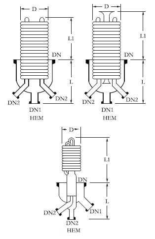
The maximum differential pressure across the coils is 3.0 bars.
| Area (m2) | DN | DN1 | DN2 | L | L1 | D | CAT. REF. |
|---|---|---|---|---|---|---|---|
| 0.4 | 150 | 40 | 25 | 200 | 200 | 145 | HEM 6 |
| 0.6 | 225 | 40 | 25 | 300 | 200 | 200 | HEM 9 |
Product Cooler
HEF product cooler is general purpose cooler, used typically for the cooling of products
from distillation columns. The cooler is connected directly to the product outlet of the
column by means of DN1. The product then flows from the top to the bottom of the unit
through the coil battery across which the cooling water flows counter currently from bottom
to top.
For connection of the cooling water inlet and outlet, we recommend the use of angled hose
connections.
| Area (m2) | DN | DN1 | DN2 | L | Type | CAT. REF. |
|---|---|---|---|---|---|---|
| 0.1 | 50 | 25 | 16 | 450 | A | HEF 1/1 |
| 0.2 | 50 | 25 | 16 | 600 | A | HEF 1/2 |
| 0.3 | 80 | 25 | 16 | 600 | A | HEF 1/3 |
| 0.35 | 100 | 25 | 19 | 600 | A | HEF 1/3.5 |
| 0.50 | 150 | 25 | 25 | 600 | B | HEF 1/5 |
| 1.00 | 150 | 25 | 25 | 850 | B | HEF 1/10 |
Hose Connector
This glass connector is used to connect flexible hose to the inlets and outlets of coil type condensers.
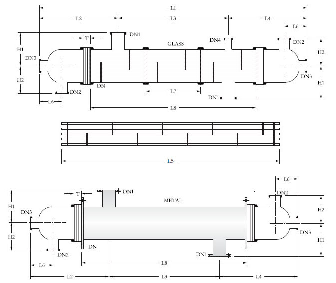
Shell And Tube Heat Exchanger
Shell and tube heat exchanger provides a versatile alternative to the coil-type heat exchnger
described in previous pages. Shell and tube heat exchanger is particularly suitable for
applications where large heat transfer area is required in relatively confined spaces. It is
equally suitable for heat transfer between two liquids or gases.
Shell & tube heat exchanger is available in single-pass as well as multi - pass.
Both versions are available with glass or mild steel shells in combination with glass tubes as
standard. Consequently, there are three basic models.
Construction Features
The glass tubes are individually sealed in the PTFE tube plates using threaded bushes. The
special construction ensures permanent tightness and easy replacement and cleaning of
tubes. Baffles on shell side ensure improved heat transfer by increased turbulence.
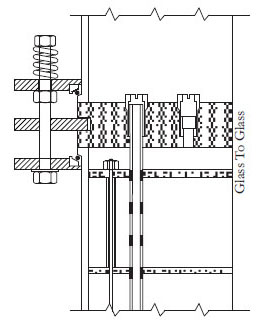
Sealing principle similar on all models :
Range Of The Models
| CAT.REF. | SHELLS | END FITTINGS | TUBES | NUMBER OF PASSES |
|---|---|---|---|---|
| RGG | Glass | Glass | Glass | 1 |
| RGM | Glass | Steel | Glass | 1/2/3 |
| RMG | Steel | Glass | Glass | 1 |
SALIENT FEATURES
CAT . REF. RGG/RGM. |
6/3 | 6/4 | 6/5 | 6/6 | 9/6 | 9/8 | 9/10 | 9/12 | 12/12 | 12/16 | 12/21 | 12/26 |
|---|---|---|---|---|---|---|---|---|---|---|---|---|
| Area (m2) | 3 | 4 | 5 | 6 | 6 | 8 | 10 | 12 | 12 | 16 | 21 | 26 |
| DN | 150 | 225 | 300 | |||||||||
| DN 1 | 80 | 100 | 150 | |||||||||
| DN 2 | 50 | 50 | 80 | |||||||||
| DN 3 | 25 | 40 | 40 | |||||||||
| DN 4 | 50 | 50 | 50 | |||||||||
| H1 | 175 | 250 | 300 | |||||||||
| H2 | 150 | 205 | 240 | |||||||||
| L1 | 2534 | 3034 | 3834 | 4534 | 2864 | 3364 | 4164 | 4864 | 2916 | 3416 | 4216 | 4916 |
| L2 | 440 | 440 | 440 | 440 | 690 | 690 | 690 | 690 | 730 | 730 | 730 | 730 |
| L3 | 1650 | 2150 | 2950 | 3650 | 1480 | 1980 | 2780 | 3480 | 1450 | 1950 | 2750 | 3450 |
| L4 | 440 | 440 | 440 | 440 | 690 | 690 | 690 | 690 | 730 | 730 | 730 | 730 |
| L5 | 2030 | 2530 | 3330 | 4030 | 2030 | 2530 | 3330 | 4030 | 2030 | 2530 | 3330 | 4030 |
| L6 | 155 | 155 | 155 | 155 | 175 | 175 | 175 | 175 | 200 | 200 | 200 | 200 |
| L7 | 1350 | 1850 | 2650 | 3350 | 1030 | 1530 | 2330 | 3030 | 1000 | 1500 | 2300 | 3000 |
| L8 | 1960 | 2460 | 3260 | 3960 | 1940 | 2440 | 3240 | 3940 | 1910 | 2410 | 3210 | 3910 |
| No. of Tubes | 37 | 73 | 151 | |||||||||
| No. of Baffles | 11 | 14 | 19 | 24 | 7 | 9 | 13 | 17 | 5 | 7 | 10 | 13 |
| T | 50 | 60 | 75 |
All glass tubes have an external diameter of 13mm or 14mm and a wall thickness of 1mm.
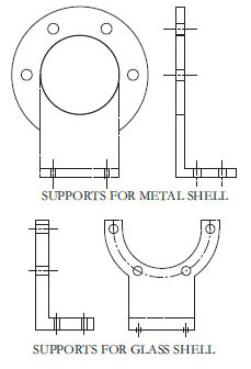
SUPPORT :
Generally two types of supports are used in shell and tube heat exchangers depending upon
MOC of shell & tube heat exchangers.
MOC of these supports is M.S.
Operating Range
The maximum permissible operating conditions in borosilicate glass 3.3heat exchangers are detailed in the table below.
Permissible Operating Pressure Ranges (bar g)
| Models | Side | DN150 | DN225 | DN300 |
|---|---|---|---|---|
| RGG | Shell | 2.0 | 1.0 | 0.75 |
| [Glass Shell/Glass Header ] | Tube | 2.0 | 1.0 | 0.75 |
| RGM | Shell | 2.0 | 1.0 | 0.75 |
| [Glass Shell/Glass Header ] | Tube | 3.0 | 3.0 | 3.05 |
| RMG | Shell | 3.5 | 3.5 | 3.5 |
| [Glass Shell/Glass Header ] | Tube | 2.0 | 1.5S | 0.75 |
Maximum operating temperature at shell and tube sides: - 40 deg C to 150 deg C.
Maximum temperature difference between the shell side and tube sides process fluids : 120 deg C.
PERFORMANCE & DESIGN DATA :
The table given below is an indication of the performance of glass shell and tube heat exchanger in several typical applications. More specific advice can be given on receipt of details.
| TYPE OF HEAT TRANSFER | BASIS |
Kcal/m2h0C |
|---|---|---|
| Liquid - Liquid Cooling | Water-water | 500-600 |
| Water- organic solvents | 250-600 | |
| Water-oil | 75-350 | |
| Water - air | 25-250 | |
| Liquid - Gas Condensation | Water-water | 600-900 |
| Water- organic solvents | 400-600 | |
| Evaporation | Steam - organic solvents | 400-600 |
| Steam-water | 500-900 |
Tab 3
Etiam id pharetra quam. Morbi tristique nunc vel sapien dapibus, sit amet imperdiet quam venenatis. Vestibulum et suscipit urna. Suspendisse volutpat quis est eu volutpat. Nulla non tortor venenatis turpis congue aliquet. Vivamus at elit vel massa elementum tempor sit amet sed odio. Nullam placerat, arcu sed ullamcorper ornare, erat erat placerat quam, in feugiat nulla purus in nunc. Maecenas vitae erat auctor, aliquam tellus et, vulputate eros.
VESSEL HOLDING RING
| Vessel holder size wise | D mm | L mm | CAT. REF. |
|---|---|---|---|
| 2 L | 100 | 15 | VRS 2 |
| 5 L | 150 | 15 | VRS 5 |
| 10 L | 215 | 15 | VRS 10 |
| 20 L | 300 | 15 | VRS 20 |
Pipeline Components
Introduction
Borosilicate glass 3.3 Pipeline Components are widely used in chemical, pharmaceutical and allied industries together with other applications such as food and drugs, dye production and electroplating industries. This is because of the special properties of borosilicate glass 3.3. 1. Smooth Surfaces allow easy cleaning and sterilization and prevent the build–up of solids on the inner walls. 2. With almost universal resistance to corrosion, a long service life is guaranteed and maintenance is kept to a minimum. 3. Their transparency permits visual monitoring of the process at all times. 4. Being inert, the risk of contamination is negligible. All the components are suitable for operation under full vacuum conditions. Non-standard size components can also be supplied on special order.
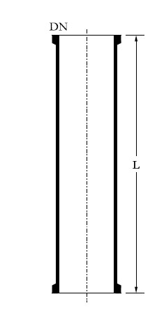
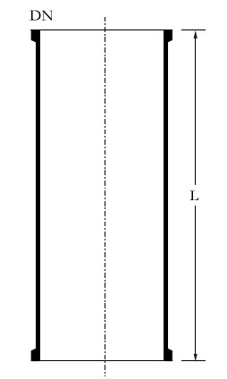
 Pipe Section
- Spacer
- Concentric reducer
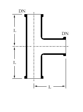
- Equal Tee
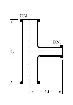
- Unequal Tee
- Bend 45°
- Bend 80°
- Bend 90°
- Bend Reducer 90°
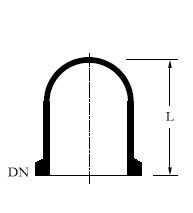
- U Bend
- U Bend With Bottom Outlet
- Bend 90°with Thermometer Branch
- Thermometer Pocket For 90° Bend
- Y Piece
- Closure
- Blind
- Equal Cross
- Unequal Cross
- Hose Connector
- Bend Hose Connector
- Jacketed Pipe Section
- Metal Jacket
Pipe Section
| L |
CAT. REF. DN 15 |
CAT. REF.
DN 25 |
CAT. REF.
DN 40 |
CAT. REF. DN 50 |
|---|---|---|---|---|
| 75 | PS07 /75 | - | - | - |
| 100 | PS07/100 | PS1/100 | PS1.5/100 | PS2/100 |
| 150 | PS07/150 | PS1/150 | PS1.5/150 | PS2/150 |
| 200 | PS07/200 | PS1/200 | PS1.5/200 | PS2/200 |
| 250 | PS07/250 | PS1/250 | PS1.5/250 | PS2/250 |
| 300 | PS07/300 | PS1/300 | PS1.5/300 | PS2/300 |
| 400 | PS07/400 | PS1/400 | PS1.5/400 | PS2/400 |
| 500 | PS07/500 | PS1/500 | PS1.5/500 | PS2/500 |
| 600 | PS07/600 | PS1/600 | PS1.5/600 | PS2/600 |
| 750 | PS07/750 | PS1/750 | PS1.5/750 | PS2/750 |
| 900 | PS07/900 | PS1/900 | PS1.5/900 | PS2/900 |
| 1000 | PS07/1000 | PS1/1000 | PS1.5/1000 | PS2/1000 |
| L |
CAT. REF.
DN 80 |
CAT. REF.
DN 100 |
CAT. REF. DN 150 |
|---|---|---|---|
| 75 | - | - | - |
| 100 | PS3/100 | PS4/100 | PS6/100 |
| 150 | PS3/150 | PS4/150 | PS6/150 |
| 200 | PS3/200 | PS4/200 | PS6/200 |
| 250 | PS3/250 | PS4/250 | PS6/250 |
| 300 | PS3/300 | PS4/300 | PS2/300 |
| 400 | PS3/400 | PS4/400 | PS6/400 |
| 500 | PS3/500 | PS4/500 | PS6/500 |
| 600 | PS3/600 | PS4/600 | PS6/600 |
| 750 | PS3/750 | PS4/750 | PS6/750 |
| 900 | PS3/900 | PS4/900 | PS6/900 |
| 1000 | PS3/1000 | PS4/1000 | PS6/1000 |
| L |
CAT. REF.
DN 225 |
CAT. REF.
DN 300 |
|---|---|---|
| 300 | PS9/300 | PS12/300 |
| 400 | PS9/400 | PS12/400 |
| 500 | PS9/500 | PS12/500 |
| 600 | PS9/600 | PS12/600 |
| 750 | PS9/750 | PS12/750 |
| 900 | PS9/900 | PS12/900 |
| 1000 | PS9/1000 | PS12/1000 |
| 1200 | PS9/1200 | PS12/1200 |
| 1500 | PS9/1500 | PS12/1500 |
| L |
CAT. REF.
DN 400 |
CAT. REF.
DN 450 |
CAT. REF. DN 600 |
|---|---|---|---|
| 300 | PS16/300 | PS18/300 | PS24/300 |
| 500 | PS16/500 | PS18/500 | PS24/500 |
| 750 | PS16/750 | PS18/750 | PS24/750 |
| 1000 | PS16/1000 | PS18/1000 | PS24/1000 |
| 1500 | PS16/1500 | PS18/1500 | PS24/1500 |
Spacer
Spacer is used to make small increments in length and is fitted between standard pipe line components . When incorporating the Spacer, longer coupling bolts are required with additional gasket.
Spacer are also available in PTFE.
| DN |
L | TYPE | CAT. REF. |
|---|---|---|---|
| 15 | 5 | A | SS07/5 |
| 15 | A | SS07/15 | |
| 20 | A | SS07/20 | |
| 25 | B | SS07/25 | |
| 50 | B | SS07/50 | |
| 25 | 5 | A | SS07/5 |
| 15 | A | SS07/15 | |
| 20 | A | SS07/20 | |
| 25 | B | SS07/25 | |
| 50 | B | SS07/50 | |
| 40 | 5 | A | SS07/5 |
| 15 | A | SS07/15 | |
| 20 | A | SS07/20 | |
| 25 | B | SS07/25 | |
| 50 | B | SS07/50 | |
| 75 | B | SS07/75 | |
| 50 | 5 | A | SS07/5 |
| 15 | A | SS07/15 | |
| 20 | A | SS07/20 | |
| 25 | B | SS07/25 | |
| 50 | B | SS07/50 | |
| 75 | B | SS07/75 | |
| 80 | 5 | A | SS07/5 |
| 15 | A | SS07/15 | |
| 20 | A | SS07/20 | |
| 25 | B | SS07/25 | |
| 50 | B | SS07/50 | |
| 75 | B | SS07/75 | |
| 100 | B | SS07/100 |
Spacer

| L |
CAT. REF. DN 15 |
CAT. REF.
DN 25 |
CAT. REF.
DN 40 |
CAT. REF. DN 50 |
|---|---|---|---|---|
| 75 | PS07 /75 | - | - | - |
| 100 | PS07/100 | PS1/100 | PS1.5/100 | PS2/100 |
| 150 | PS07/150 | PS1/150 | PS1.5/150 | PS2/150 |
| 200 | PS07/200 | PS1/200 | PS1.5/200 | PS2/200 |
| 250 | PS07/250 | PS1/250 | PS1.5/250 | PS2/250 |
| 300 | PS07/300 | PS1/300 | PS1.5/300 | PS2/300 |
| 400 | PS07/400 | PS1/400 | PS1.5/400 | PS2/400 |
| 500 | PS07/500 | PS1/500 | PS1.5/500 | PS2/500 |
| 600 | PS07/600 | PS1/600 | PS1.5/600 | PS2/600 |
| 750 | PS07/750 | PS1/750 | PS1.5/750 | PS2/750 |
| 900 | PS07/900 | PS1/900 | PS1.5/900 | PS2/900 |
| 1000 | PS07/1000 | PS1/1000 | PS1.5/1000 | PS2/1000 |
| L |
CAT. REF.
DN 80 |
CAT. REF.
DN 100 |
CAT. REF. DN 150 |
|---|---|---|---|
| 75 | - | - | - |
| 100 | PS3/100 | PS4/100 | PS6/100 |
| 150 | PS3/150 | PS4/150 | PS6/150 |
| 200 | PS3/200 | PS4/200 | PS6/200 |
| 250 | PS3/250 | PS4/250 | PS6/250 |
| 300 | PS3/300 | PS4/300 | PS2/300 |
| 400 | PS3/400 | PS4/400 | PS6/400 |
| 500 | PS3/500 | PS4/500 | PS6/500 |
| 600 | PS3/600 | PS4/600 | PS6/600 |
| 750 | PS3/750 | PS4/750 | PS6/750 |
| 900 | PS3/900 | PS4/900 | PS6/900 |
| 1000 | PS3/1000 | PS4/1000 | PS6/1000 |
| L |
CAT. REF.
DN 225 |
CAT. REF.
DN 300 |
|---|---|---|
| 300 | PS9/300 | PS12/300 |
| 400 | PS9/400 | PS12/400 |
| 500 | PS9/500 | PS12/500 |
| 600 | PS9/600 | PS12/600 |
| 750 | PS9/750 | PS12/750 |
| 900 | PS9/900 | PS12/900 |
| 1000 | PS9/1000 | PS12/1000 |
| 1200 | PS9/1200 | PS12/1200 |
| 1500 | PS9/1500 | PS12/1500 |
| L |
CAT. REF.
DN 400 |
CAT. REF.
DN 450 |
CAT. REF. DN 600 |
|---|---|---|---|
| 300 | PS16/300 | PS18/300 | PS24/300 |
| 500 | PS16/500 | PS18/500 | PS24/500 |
| 750 | PS16/750 | PS18/750 | PS24/750 |
| 1000 | PS16/1000 | PS18/1000 | PS24/1000 |
| 1500 | PS16/1500 | PS18/1500 | PS24/1500 |
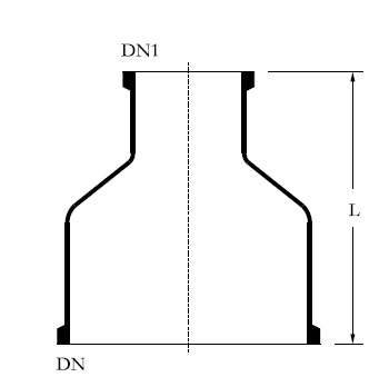
Concentric Reducer
| DN |
DN1 | L | CAT. REF. |
|---|---|---|---|
| 25 |
15 | 75 | PR1/07 |
| 40 | 15 | 100 | PR1.5/07 |
| 40 | 25 | 100 | PR1.5/1 |
| 50 | 15 | 100 | PR2/07 |
| 50 | 25 | 100 | PR2/1 |
| 50 | 40 | 100 | PR2/1.5 |
| 80 | 15 | 100 | PR3/07 |
| 80 | 25 | 125 | PR3/1 |
| 80 | 40 | 125 | PR3/1.5 |
| 80 | 50 | 125 | PR3/2 |
| 100 | 15 | 150 | PR4/07 |
| 100 | 25 | 150 | PR4/1 |
| 100 | 40 | 150 | PR4/1.5 |
| 100 | 50 | 150 | PR4/2 |
| 100 | 80 | 200 | PR4/3 |
| 150 | 25 | 200 | PR6/1 |
| 150 | 40 | 200 | PR6/1.5 |
| 150 | 50 | 200 | PR6/2 |
| 150 | 80 | 200 | PR6/3 |
| 150 | 100 | 250 | PR6/4 |
| 225 | 25 | 250 | PR9/1 |
| 225 | 40 | 250 | PR9/1.5 |
| 225 | 50 | 250 | PR9/2 |
| 225 | 80 | 250 | PR9/3 |
| 225 | 100 | 250 | PR9/4 |
| 225 | 150 | 300 | PR9/6 |
| 225 | 25 | 300 | PR12/1 |
| 300 | 40 | 300 | PR12/1.5 |
| 300 | 50 | 300 | PR12/2 |
| 300 | 80 | 300 | PR12/3 |
| 300 | 100 | 300 | PR12/4 |
| 300 | 150 | 300 | PR12/6 |
| 300 | 225 | 300 | PR12/9 |
| 400 | 25 | 350 | PR16/1 |
| 400 | 40 | 350 | PR16/1.5 |
| 400 | 50 | 350 | PR16/2 |
| 400 | 80 | 350 | PR16/3 |
| 400 | 100 | 350 | PR16/4 |
| 400 | 150 | 350 | PR16/6 |
| 400 | 225 | 350 | PR16/9 |
| 400 | 300 | 350 | PR16/12 |
| 450 | 25 | 350 | PR18/1 |
| 450 | 40 | 350 | PR18/1.5 |
| 450 | 50 | 375 | PR18/2 |
| 450 | 80 | 375 | PR18/3 |
| 450 | 100 | 375 | PR18/4 |
| 450 | 150 | 375 | PR18/6 |
| 450 | 225 | 375 | PR18/9 |
| 450 | 300 | 375 | PR18/12 |
| 600 | 100 | 400 | PR24/4 |
| 600 | 150 | 400 | PR24/6 |
| 600 | 225 | 425 | PR24/9 |
| 600 | 300 | 425 | PR24/12 |
| 600 | 450 | 475 | PR24/18 |
* This unit is also available in cylindrical vessel .
* Heating Mantel is also available in the same unit , please specify before the order.
Equal Tee
| DN | L | CAT. REF. |
|---|---|---|
| 15 | 50 | PT07 |
| 25 | 100 | PT1 |
| 40 | 150 | PT1.5 |
| 50 | 150 | PT2 |
| 80 | 200 | PT3 |
| 100 | 250 | PT4 |
| 150 | 250 | PT6 |
| 225 | 375 | PT9 |
| 300 | 450 | PT12 |
UnEqual Tee
| DN |
DN1 | L | L1 | CAT. REF. |
|---|---|---|---|---|
| 25 |
15 | 150 | 75 | PTU1/07 |
| 40 | 15 | 200 | 75 | PTU1.5/07 |
| 40 | 25 | 200 | 75 | PTU1.5/1 |
| 50 | 15 | 200 | 80 | PTU2/07 |
| 50 | 25 | 200 | 80 | PTU2/1 |
| 50 | 40 | 200 | 100 | PTU2/1.5 |
| 80 | 15 | 250 | 100 | PTU3/07 |
| 80 | 25 | 250 | 100 | PTU3/1 |
| 80 | 40 | 250 | 100 | PTU3/1.5 |
| 80 | 50 | 250 | 125 | PTU3/2 |
| 100 | 15 | 250 | 100 | PTU4/07 |
| 100 | 25 | 250 | 110 | PTU4/1 |
| 100 | 40 | 250 | 120 | PTU4/1.5 |
| 100 | 50 | 250 | 120 | PTU4/2 |
| 100 | 80 | 300 | 125 | PTU4/3 |
| 150 | 25 | 250 | 150 | PTU6/1 |
| 150 | 40 | 250 | 150 | PTU6/1.5 |
| 150 | 50 | 250 | 150 | PTU6/2 |
| 150 | 80 | 300 | 200 | PTU6/3 |
| 150 | 100 | 300 | 200 | PTU6/4 |
| 225 | 25 | 300 | 185 | PTU9/1 |
| 225 | 40 | 300 | 185 | PTU9/1.5 |
| 225 | 50 | 300 | 185 | PTU9/2 |
| 225 | 80 | 300 | 210 | PTU9/3 |
| 225 | 100 | 450 | 250 | PTU9/4 |
| 225 | 150 | 450 | 275 | PTU9/6 |
| 300 | 25 | 400 | 230 | PTU12/1 |
| 300 | 40 | 400 | 230 | PTU12/1.5 |
| 300 | 50 | 400 | 230 | PTU12/2 |
| 300 | 80 | 400 | 275 | PTU12/3 |
| 300 | 100 | 400 | 275 | PTU12/4 |
| 300 | 150 | 450 | 300 | PTU12/6 |
| 300 | 225 | 600 | 300 | PTU12/9 |
| 400 | 40 | 400 | 275 | PTU16/1.5 |
| 400 | 50 | 400 | 275 | PTU16/2 |
| 400 | 80 | 400 | 300 | PTU16/3 |
| 400 | 100 | 400 | 300 | PTU16/4 |
| 400 | 150 | 500 | 350 | PTU16/6 |
| 400 | 225 | 800 | 450 | PTU16/9 |
| 400 | 300 | 800 | 450 | PTU16/12 |
| 450 | 40 | 400 | 300 | PTU18/1.5 |
| 450 | 50 | 400 | 300 | PTU18/2 |
| 450 | 80 | 400 | 320 | PTU18/3 |
| 450 | 100 | 400 | 320 | PTU18/4 |
| 450 | 150 | 600 | 380 | PTU18/6 |
| 450 | 225 | 800 | 400 | PTU18/9 |
| 450 | 300 | 800 | 400 | PTU18/12 |
| 600 | 100 | 600 | 450 | PTU24/4 |
| 600 | 150 | 600 | 450 | PTU24/6 |
| 600 | 225 | 800 | 525 | PTU24/9 |
| 600 | 300 | 800 | 525 | PTU24/12 |
BEND 45°dddddddddddddddddddd
| DN | L | TYPE | CAT. REF. |
|---|---|---|---|
| 15 | 50 | A | PB07/45° |
| 25 | 75 | A | PB1/45° |
| 40 | 100 | A | PB1.5/45° |
| 50 | 100 | A | PB2/45° |
| 80 | 125 | B | PB3/45° |
| 100 | 175 | B | PB4/45° |
| 150 | 200 | B | PB6/45° |
| 225 | 225 | B | PB9/45° |
| 300 | 275 | B | PB12/45° |
BEND 45°
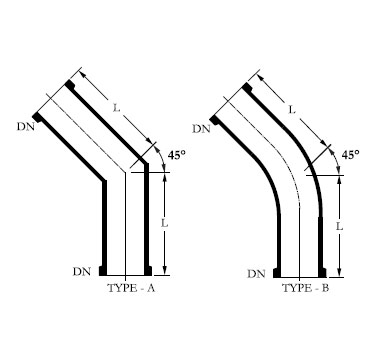
| DN | L | TYPE | CAT. REF. |
|---|---|---|---|
| 15 | 50 | A | PB07/45° |
| 25 | 75 | A | PB1/45° |
| 40 | 100 | A | PB1.5/45° |
| 50 | 100 | A | PB2/45° |
| 80 | 125 | B | PB3/45° |
| 100 | 175 | B | PB4/45° |
| 150 | 200 | B | PB6/45° |
| 225 | 225 | B | PB9/45° |
| 300 | 275 | B | PB12/45° |
BEND 80°
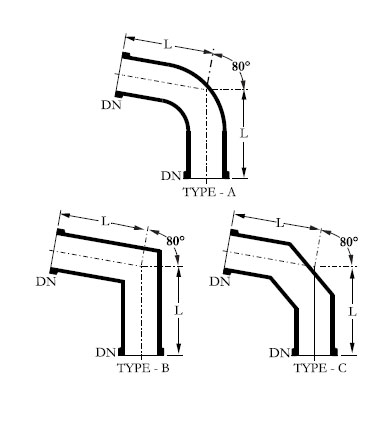
| DN | L | TYPE | CAT. REF. |
|---|---|---|---|
| 15 | 100 | A | PB07/80° |
| 25 | 100 | A | PB1//80° |
| 40 | 150 | A | PB1.5/80° |
| 50 | 150 | A | PB2/80° |
| 80 | 200 | B/C | PB3/80° |
| 100 | 250 | B/C | PB4/80° |
| 150 | 250 | B/C | PB6/80° |
| 225 | 375 | B/C | PB9/80° |
| 300 | 450 | B/C | PB12/80° |
BEND 90°
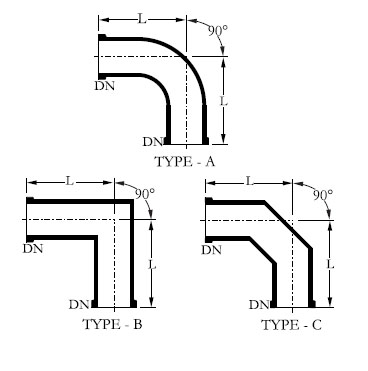
| DN | L | TYPE | CAT. REF. |
|---|---|---|---|
| 15 | 100 | A | PB07/90° |
| 25 | 100 | A | PB1//90° |
| 40 | 150 | A | PB1.5/90° |
| 50 | 150 | A | PB2/90° |
| 80 | 200 | B/C | PB3/90° |
| 100 | 250 | B/C | PB4/90° |
| 150 | 250 | B/C | PB6/90° |
| 225 | 375 | B/C | PB9/90° |
| 300 | 450 | B/C | PB12/90° |
Bend Reducer 90°
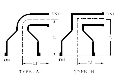
| DN | DN1 | L | L1 | CAT. REF. |
|---|---|---|---|---|
| 40 | 25 | 150 | 125 | PBR1.5/1 |
| 50 | 25 | 150 | 150 | PBR2/1 |
| 50 | 40 | 150 | 150 | PBR2/1.5 |
| 80 | 40 | 150 | 150 | PBR3/1.5 |
| 80 | 50 | 150 | 150 | PBR3/2 |
| 100 | 25 | 200 | 150 | PBR4/1 |
| 100 | 50 | 200 | 150 | PBR4/2 |
| 100 | 80 | 200 | 175 | PBR4/3 |
| 150 | 50 | 200 | 150 | PBR6/2 |
| 150 | 80 | 250 | 175 | PBR6/3 |
| 225 | 50 | 250 | 200 | PBR9/2 |
| 225 | 80 | 250 | 250 | PBR9/3 |
| 300 | 80 | 300 | 250 | PBR12/3 |
| 300 | 150 | 300 | 250 | PBR12/6 |
U BEND
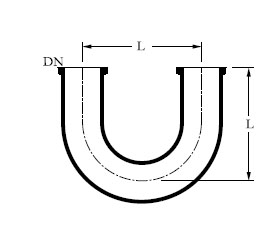
| DN | L | CAT. REF. |
|---|---|---|
| 15 | 75 | PU07 |
| 25 | 150 | PU1 |
| 40 | 175 | PU1.5 |
| 50 | 175 | PU2 |
| 80 | 225 | PU3 |
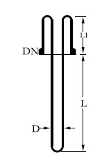
U Bend With Bottom Outlet
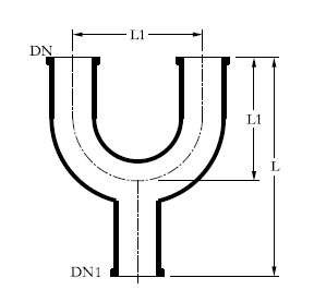
| DN | L | CAT. REF. |
|---|---|---|
| 15 | 75 | PU07 |
| 25 | 150 | PU1 |
| 40 | 175 | PU1.5 |
| 50 | 175 | PU2 |
| 80 | 225 | PU3 |
Bend 90°with Thermometer Branch
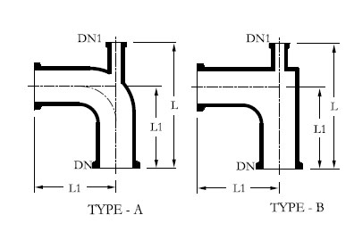
| DN | DN1 | L | L1 | CAT. REF. |
|---|---|---|---|---|
| 15 | 15 | 125 | 75 | PUO07 |
| 25 | 25 | 250 | 150 | PUO1 |
| 40 | 25 | 275 | 175 | PUO1.5/1 |
| 40 | 40 | 275 | 175 | PUO1.5 |
| 50 | 25 | 275 | 175 | PUO2/1 |
| 50 | 50 | 275 | 175 | PUO2 |
| 80 | 25 | 350 | 125 | PUO3/1 |
Thermometer Pocket For 90° Bend
| DN | DN1 | L | L1 | TYPE | CAT. REF. |
|---|---|---|---|---|---|
| 40 | 25 | 225 | 150 | A | PBT1.5 |
| 50 | 25 | 225 | 150 | A | PBT2 |
| 80 | 25 | 275 | 200 | A | PBT3 |
| 100 | 25 | 350 | 250 | B | PBT4 |
| 150 | 25 | 350 | 250 | B | PBT6 |
| 225 | 25 | 475 | 375 | B | PBT9 |
| 300 | 25 | 550 | 450 | B | PBT12 |
Y Piece
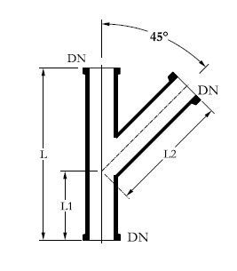
| DN | DL | L1 | L2 | CAT. REF. |
|---|---|---|---|---|
| 15 | 125 | 50 | 100 | PY07 |
| 25 | 200 | 75 | 150 | PY1 |
| 40 | 250 | 100 | 175 | PY1.5 |
| 50 | 300 | 125 | 200 | PY2 |
| 80 | 350 | 150 | 250 | PY3 |
| 100 | 400 | 150 | 350 | PY4 |
Closure
| DN | L1 | CAT. REF. |
|---|---|---|
| 15 | 40 | PBE07 |
| 25 | 50 | PBE1 |
| 40 | 75 | PBE1.5 |
| 50 | 75 | PBE2 |
| 80 | 100 | PBE3 |
| 100 | 125 | PBE4 |
| 150 | 125 | PBE6 |
| 225 | 150 | PBE9 |
| 300 | 150 | PBE12 |
BLIND
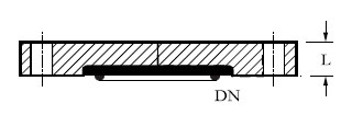
| DN | L | CAT. REF. |
|---|---|---|
| 15 | 8 | PBF07 |
| 25 | 8 | PBF1 |
| 40 | 8 | PBF1.5 |
| 50 | 8 | PBF2 |
| 80 | 8 | PBF3 |
| 100 | 8 | PBF4 |
| 150 | 8 | PBF6 |
| 225 | 8 | PBF9 |
| 300 | 8 | PBF12 |
Equal Cross
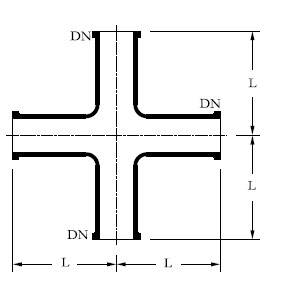
| DN | L | CAT. REF. |
|---|---|---|
| 15 | 50 | PX07 |
| 25 | 100 | PX1 |
| 40 | 150 | PX1.5 |
| 50 | 150 | PX2 |
| 80 | 200 | PX3 |
| 100 | 250 | PX4 |
| 150 | 250 | PX6 |
Unequal Cross
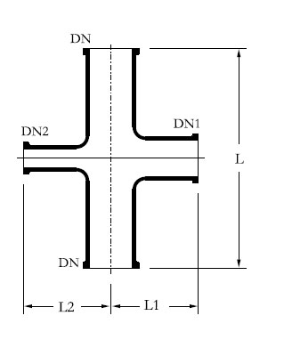
| DN | DN1 | DN2 | L | L1 | L2 | CAT. REF. |
|---|---|---|---|---|---|---|
| 50 | 25 | 25 | 200 | 80 | 80 | PXU2/1/1 |
| 50 | 40 | 25 | 200 | 100 | 80 | PXU2/1.5/1 |
| 80 | 25 | 25 | 250 | 100 | 100 | PXU3/1/1 |
| 80 | 40 | 25 | 250 | 100 | 100 | PXU3/1.5/1 |
| 80 | 50 | 25 | 250 | 115 | 100 | PXU3/2/1 |
| 100 | 25 | 25 | 250 | 110 | 110 | PXU4/1/1 |
| 100 | 40 | 25 | 250 | 125 | 110 | PXU4/1.5/1 |
| 100 | 50 | 25 | 250 | 125 | 110 | PXU4/2/1 |
| 100 | 80 | 25 | 300 | 150 | 150 | PXU4/3/1 |
| 150 | 40 | 25 | 250 | 150 | 150 | PXU6/1.5/1 |
| 150 | 50 | 25 | 250 | 150 | 150 | PXU6/2/1 |
| 150 | 80 | 50 | 300 | 175 | 150 | PXU6/3/2 |
| 150 | 100 | 50 | 300 | 200 | 150 | PXU6/4/2 |
| 225 | 40 | 40 | 300 | 185 | 185 | PXU9/1.5/1.5 |
| 225 | 50 | 40 | 300 | 185 | 185 | PXU9/2/1.5 |
| 225 | 80 | 40 | 300 | 210 | 185 | PXU9/3/1.5 |
| 225 | 100 | 50 | 450 | 250 | 185 | PXU9/4/2 |
| 225 | 150 | 80 | 450 | 275 | 210 | PXU9/6/3 |
| 300 | 50 | 40 | 400 | 230 | 230 | PXU12/2/1.5 |
| 300 | 80 | 40 | 400 | 275 | 230 | PXU12/3/1.5 |
| 300 | 100 | 40 | 400 | 275 | 230 | PXU12/4/1.5 |
| 300 | 150 | 50 | 450 | 300 | 230 | PXU12/6/2 |
| 300 | 225 | 80 | 600 | 300 | 275 | PXU12/9/3 |
| 400 | 40 | 40 | 400 | 275 | 275 | PXU16/1.5/1.5 |
| 400 | 80 | 40 | 400 | 300 | 275 | PXU16/3/1.5 |
| 400 | 100 | 40 | 400 | 300 | 275 | PXU16/4/1.5 |
400 |
150 | 80 | 500 | 350 | 300 | PXU16/6/3 |
400 |
225 | 100 |
800 | 450 | 300 | PXU16/9/4 |
| 450 | 40 | 40 | 400 | 300 | 300 | PXU18/1.5/1.5 |
| 450 | 80 | 40 | 400 | 320 | 300 | PXU18/3/1.5 |
| 450 | 100 | 40 | 400 | 320 | 300 | PXU18/4/1.5 |
| 450 | 150 | 80 | 600 | 380 | 320 | PXU18/6/3 |
| 450 | 225 | 100 | 800 | 400 | 320 | PXU18/9/4 |
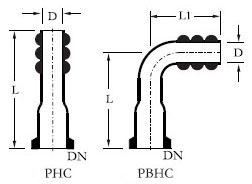
Hose Connector
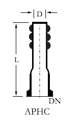
| DN | D | L | CAT. REF. |
|---|---|---|---|
| 15 | 19 | 70 | PHC07/.75 |
| 25 | 25 | 90 | PHC1/1 |
| 25 | 19 | 90 | PHC1/.75 |
| 25 | 13 | 90 | PHC1/.5 |
| 25 | 07 | 90 | PHC1/.25 |
| 40 | 25 | 100 | PHC1.5/1 |
| 40 | 19 | 100 | PHC1.5/.75 |
Bend Hose Connector
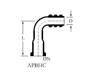
| DN | D | L | CAT. REF. |
|---|---|---|---|
| 15 | 19 | 40 | PBHC7/.75 |
| 25 | 25 | 60 | PBHC1/1 |
| 25 | 19 | 60 | PBHC1/.75 |
| 40 | 25 | 75 | PBHC1.5/.75 |
| 50 | 19 | 100 | PBHC2/.75 |
*D is the bore of the matching hose .
Jacketed Pipe Section
For heating of piping and for controlling the temperature throughout the column, the jacketed pipe section is provided. Glass jacket is sealed to the pipe section using silicon 'O' ring and other sealing compositions.
*Permissible pressure in glass jacket
DN 80 - DN 150 1.0 bar. g
DN 225 - DN 300 0.5 bar. g
| DN | D | DN1 | L | L1 | L2 | CAT. REF. |
|---|---|---|---|---|---|---|
| 80 | 100 | 25 | 1000 | 850 | 750 | PSD3/1000 |
| 100 | 150 | 25 | 1000 | 850 | 750 | PSD4/1000 |
| 150 | 225 | 25 | 1000 | 850 | 700 | PSD6/1000 |
| 225 | 300 | 25 | 1000 | 850 | 700 | PSD9/1000 |
| 300 | 400 | 25 | 1000 | 850 | 650 | PSD12/1000 |
Metal Jacket
Pipe section can also be provided with Metal Jacket. In Metal Jacket, maximum operating pressure permitted is 2.0 bar g in all the sizes. They are used not only to avoid heat loss for the purpose of saving energy but also where product temperature has to be maintained to prevent crystallising or undesirable reactions.
| DN | D | DN1 | L | L1 | L2 | CAT. REF. |
|---|---|---|---|---|---|---|
| 80 | 100 | 25 | 1000 | 850 | 750 | PSJ3/1000 |
| 100 | 135 | 25 | 1000 | 850 | 750 | PSJ4/1000 |
| 150 | 188 | 25 | 1000 | 850 | 700 | PSJ6/1000 |
| 225 | 262 | 25 | 1000 | 850 | 700 | PSJ9/1000 |
| 300 | 345 | 25 | 1000 | 850 | 650 | PSJ12/1000 |
Vessels & Stirrers
Introduction
In the majority of glass plant installations, vessels find universal applications as reactors, re-boilers, receivers and separators as well as for storage, feed or measuring.
Vessels are available in spherical & cylindrical shape form 5 to 500 liter capacity. All vessels are provided with bottom outlet nozzle for which a suitable valve can be selected form the range of valves. Both spherical and cylindrical vessels can be supplied with graduation to special order.
Cylindrical vessel can be supplied with glass / Metal Jacket also.
- Spherical Vessels General Data
- Single Neck Spherical Vessel
- Three Neck Bottom Outlet Spherical Vessel
- Four Neck Bottom Outlet Spherical Vessel
- Five Neck Bottom Outlet Spherical Vessel
- Spherical Vessel with Nozzel at 90°
- Receiver Spherical Vessel
- Addition Spherical Vessel
- Wide Bottom Outlet Spherical Vessel
- Cyclone Spherical Vessel
- Vessel with bottom outlet valve seat
- Cylindrical Vessel
- Cylindrical Vessel Cover
- Cylindrical Receiver Vessel
- Cylindrical Flask
- Aspirator Bottle
- Vessel Holder
- Dip Pipe
- Short Dip Pipe
- Gas Sparger
- Thermometer Pocket
- Stirrers
- Chuck & Seal Assembly
- Glass Stirrer with Teflon Blade
- Vortex Stirrer
- Propeller Stirrer
- PTFE Stirrer
- Stirring assembly with bellow seal
- Stirrer assembly with mechanical seal
- Stirrer Drive Motor ( Non- Flame Proof)
- Speed Variator ( Drive )
- Baths
- Heating Bath Jacketed with Coil & Heater
- Cooling Bath
- Heating Mantle
- Measurement & control
- Two Point Digital Temperature Indicator
- Continuous Temperature Controller
- Decantor (separator)
Spherical Vessels General Data
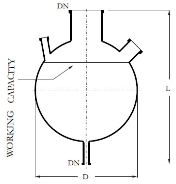
| Nominal Cap. Ltr. | Bulb Cap. Ltr. | Working Cap. Ltr. | Maximum Internal Pressure (bar G.) |
|---|---|---|---|
| 5L | 5L | 4L | 1.0 |
| 10 L | 10 L | 9 L | 0.8 |
| 20 L | 21 L | 20 L | 0.7 |
| 50 L | 62 L | 58 L | 0.5 |
| 100 L | 118 L | 111 L | 0.4 |
| 200 L | 212 L | 200 L | 0.25 |
| 300 L | 315 L | 300 L | 0.2 |
| Nominal Cap. Ltr. | Bulb Diameter in MM (D) | Vessel Length in MM (L) | Tolerance in Diameter mm | Tolerance in Length mm L |
|---|---|---|---|---|
| 5L | 223 | 425 | ±2 | ±5 |
| 10 L | 285 | 500 | ±2 | ±5 |
| 20 L | 350 | 575 | ±2 | ±5 |
| 50 L | 490 | 800 | ±3 | ±5 |
| 100 L | 600 | 900 | ±5 | ±10 |
| 200 L | 750 | 1100 | ±5 | ±15 |
| 300 L | 860 | 1175 | ±6 | ±15 |
500 Liter vessel on request.
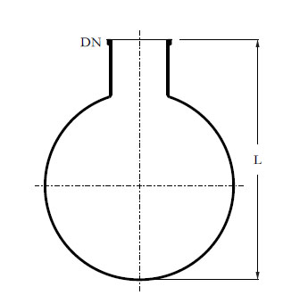
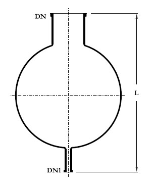
Single Neck Spherical Vessel
| Nominal Cap. Ltr. | DN mm | L mm | CAT. REF. |
|---|---|---|---|
| 5L | 50 | 300 | VSA5 |
| 10 L | 80 | 375 | VSA10 |
| 20 L | 100 | 450 | VSA20 |
| 50 L | 150 | 600 | VSA50 |
| 100 L | 225 | 700 | VSA100 |
| 200 L | 300 | 900 | VSA200 |
| 300 L | 400 | 1000 | VSA300 |
Tolerance ±as per given general data in the vessel chapter.
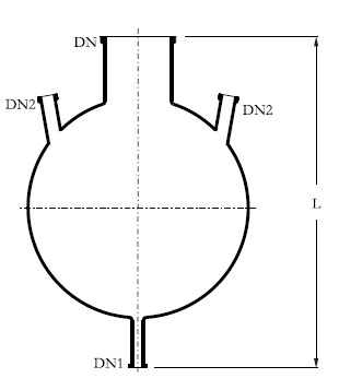
Three Neck Bottom Outlet Spherical Vessel
| Nominal Cap. Ltr. | DN mm | DN1 mm | DN2 mm | L mm | CAT. REF. |
|---|---|---|---|---|---|
| 5L | 50 | 25 | 25 | 425 | VSA5 |
| 10 L | 80 | 25 | 25 | 500 | VSA10 |
| 20 L | 100 | 25 | 25 | 575 | VSA20 |
| 50 L | 150 | 40 | 40 | 800 | VSA50 |
| 100 L | 225 | 40 | 40 | 900 | VSA100 |
| 200 L | 300 | 40 | 40 | 1100 | VSA200 |
| 300 L | 400 | 50 | 50 | 1175 | VSA300 |
Tolerance ±as per given general data in the vessel chapter.
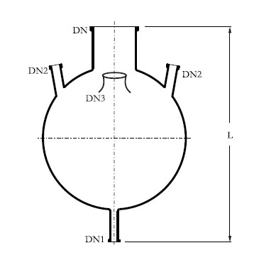
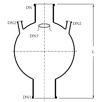
Four Neck Bottom Outlet Spherical Vessel
| Nominal Cap. Ltr. | DN mm | DN1 mm | DN2 mm | DN3 mm | L mm | CAT. REF. |
|---|---|---|---|---|---|---|
| 5L | 50 | 25 | 25 | 40 | 425 | VSP5 |
| 10 L | 80 | 25 | 25 | 40 | 500 | VSP10 |
| 20 L | 100 | 25 | 25 | 40 | 575 | VSP20 |
| 50 L | 150 | 40 | 40 | 100 | 800 | VSP50 |
| 100 L | 225 | 40 | 40 | 100 | 900 | VSP100 |
| 200 L | 300 | 40 | 40 | 100 | 1100 | VSP200 |
| 300 L | 400 | 50 | 50 | 100 | 1175 | VSP300 |
Tolerance ±as per given general data in the vessel chapter.
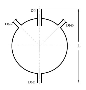
Five Neck Bottom Outlet Spherical Vessel
| Nominal Cap. Ltr. | DN mm | DN1 mm | DN2 mm | DN3 mm | L mm | CAT. REF. |
|---|---|---|---|---|---|---|
| 5L | 50 | 25 | 25 | 40 | 425 | VSL5 |
| 10 L | 80 | 25 | 25 | 40 | 500 | VSL10 |
| 20 L | 100 | 25 | 25 | 40 | 575 | VSL20 |
| 50 L | 150 | 40 | 40 | 100 | 800 | VSL50 |
| 100 L | 225 | 40 | 40 | 100 | 900 | VSL100 |
| 200 L | 300 | 40 | 40 | 100 | 1100 | VSL200 |
| 300 L | 400 | 50 | 50 | 100 | 1175 | VSL300 |
Tolerance ±as per given general data in the vessel chapter.
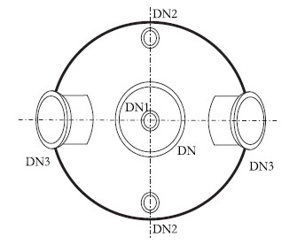
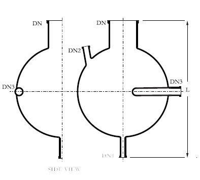
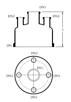
Spherical Vessel with Nozzel at 90°
This vessel is used in circulatory boiler systems. Additional nozzles can be provided on the equator on request for special requirement
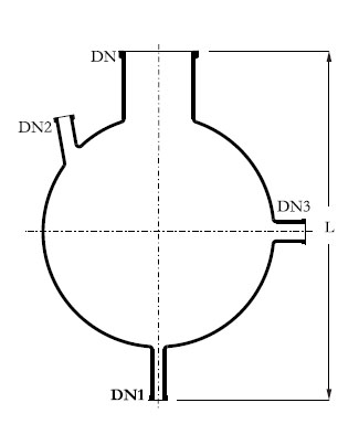
| Nominal Cap. Ltr. | DN mm | DN1 mm | DN2 mm | DN3 mm | L mm | CAT. REF. |
|---|---|---|---|---|---|---|
| 5L | 50 | 25 | 25 | 40 | 425 | VSD5 |
| 10 L | 80 | 25 | 25 | 40 | 500 | VSD10 |
| 20 L | 100 | 25 | 25 | 40 | 575 | VSD20 |
| 50 L | 150 | 40 | 40 | 100 | 800 | VSD50 |
| 100 L | 225 | 40 | 40 | 100 | 900 | VSD100 |
| 200 L | 300 | 40 | 40 | 100 | 1100 | VSD200 |
| 300 L | 400 | 50 | 50 | 100 | 1175 | VSD300 |
Tolerance ±as per given general data in the vessel chapter.
Receiver Spherical Vessel
Receiver is provided with built in dip pipe. This is to be supported on a vessel holding ring.
| Nominal Cap. Ltr. | DN mm | DN1 mm | DN2 45° | DN3 45° | L mm | CAT. REF. |
|---|---|---|---|---|---|---|
| 5L | 25 | 25 | 25 | - | 350 | VR5 |
| 10 L | 25 | 25 | 25 | - | 425 | VR10 |
| 20 L | 25 | 25 | 25 | - | 500 | VR20 |
| 5 L | 25 | 25 | 25 | 25 | 350 | VRB5 |
| 10 L | 25 | 25 | 25 | 25 | 425 | VRB10 |
| 20 L | 25 | 25 | 25 | 25 | 500 | VRB20 |
Tolerance ±as per given general data in the vessel chapter.
Addition Spherical Vessel
This vessel is provided with a short bottom outlet , it should be supported on vessel holder / holding ring.
Tolerance ±as per given general data in the vessel chapter.
| Nominal Cap. Ltr. | DN mm | DN1 mm | L mm | CAT. REF. |
|---|---|---|---|---|
| 5L | 50 | 25 | 375 | VA5 |
| 10 L | 80 | 25 | 435 | VA10 |
| 20 L | 100 | 25 | 510 | VA20 |
| 50 L | 150 | 40 | 675 | VA50 |
| 100 L | 225 | 40 | 775 | VA100 |
| 200 L | 300 | 40 | 975 | VA200 |
| 300 L | 400 | 100 | 1075 | VA300 |
Tolerance ±as per given general data in the vessel chapter.
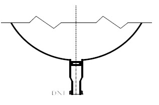
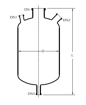
Wide Bottom Outlet Spherical Vessel
This vessel is used to fit immersion heat exchanger at the bottom.
| Nominal Cap. Ltr. | DN mm | DN1 mm | DN2 mm | DN3 mm | L mm | CAT. REF. |
|---|---|---|---|---|---|---|
| 5L | 150 | 150 | 40 | 100 | 800 | VSR50 |
| 10 L | 225 | 150 | 40 | 100 | 900 | VSR100 |
| 20 L | 300 | 150 | 40 | 100 | 1150 | VSR200 |
| 50 L | 150 | 225 | 40 | 100 | 820 | VSE50 |
| 100 L | 225 | 225 | 40 | 100 | 950 | VSE100 |
| 200 L | 300 | 225 | 40 | 100 | 1200 | VSE200 |
Tolerance ±as per given general data in the vessel chapter.
Cyclone Spherical Vessel
Cyclone is used for the separation of droplets and solids from gases and vapours. Cyclone
is supported on a vessel holder. A dip pipe is used on the top neck.
| Nominal Cap. Ltr. | DN mm | DN1 mm | DN2 mm | DN3 mm | L mm | CAT. REF. |
|---|---|---|---|---|---|---|
| 5L | 50 | 25 | 25 | 40 | 425 | VSCY5 |
| 10 L | 80 | 25 | 25 | 40 | 500 | VSCY10 |
| 20 L | 100 | 25 | 25 | 50 | 575 | VSCY20 |
| 50 L | 150 | 40 | 40 | 50 | 800 | VSCY50 |
Tolerance ±as per given general data in the vessel chapter.
Vessel with bottom outlet valve seat
To fit a bottom outlet valve (BAL type) all spherical and cylindrical vessel can be supplied with valve seat in bottom outlet. For this, Add a suffix "/B"o the catalouge reference of a vessel, for e.g. 'VSL50' should be mentioned as 'VSL50/B'.
NOTES ON USE OF SPHERICAL VESSEL:
Cylindrical Vessel
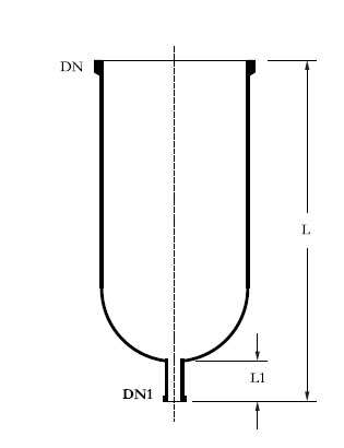
Cylindrical Vessels can be used for various applications such as reaction, separating receiver, feeding etc. 50 liter and above Cylindrical Vessels need to be supported in a vessel holder.
Tolerance ±as per given general data in the vessel chapter.
| Nominal Cap. Ltr. | DN mm | DN1 mm | Lmm | L1mm | CAT. REF. |
|---|---|---|---|---|---|
| 5L | 100 | 25 | 700 | 60 | VZ5/4 |
| 5L | 150 | 25 | 460 | 60 | VZ5/6 |
| 10 L | 150 | 25 | 700 | 60 | VZ10/6 |
| 20 L | 225 | 25 | 750 | 60 | VZ20/9 |
| 30 L | 300 | 40 | 650 | 65 | VZ30/12 |
| 50 L | 300 | 40 | 915 | 65 | VZ50/12 |
| 100 L | 450 | 40 | 900 | 65 | VZ100/18 |
| 100 L | 450 | 40 | 1200 | 65 | VZ150/16 |
| 200 L | 450 | 40 | 1500 | 65 | VZ200/18 |
| 300 L | 600 | 50 | 1300 | 65 | VZ300/24 |
| 400 L | 600 | 50 | 1650 | 65 | VZ300/24 |
Tolerance ±as per given general data in the vessel chapter. If need the graduation marking on the vessel, please mention the "G" with catalogue code. The same vessel can be supplied in reduced top neck.
Cylindrical Vessel Cover
| Nominal Cap. Ltr. | DN mm | DN1 mm | DN2mm | Lmm | CAT. REF. |
|---|---|---|---|---|---|
| 5L | 100 | - | 2 x 25 | 200 | VZA5/4 |
| 5L | 150 | 50 | 2 x 25 | 200 | VZA5/6 |
| 10 L | 150 | 50 | 3 x 25 | 200 | VZA10/6 |
| 20 L | 225 | 50 | 3 x 25 | 250 | VZA20/9 |
| 30 L | 300 | 50 | 3 x 40 | 250 | VZA30/12 |
| 50 L | 300 | 80 | 3 x 50 | 250 | VZA50/12 |
| 50 L | 300 | 40 | 3 x 40 | 250 | |
| 100 L | 450 | 50 | 3 x 40 | 275 | VZA100/18 |
| 450 | 80 | 3 x 40 | 275 | ||
| 450 | 100 | 3 x 40 | 275 | ||
| 150 L | 400 | 100 | 3 x 40 | 275 | VAZ150/16 |
| 200 L | 450 | 100 | 3 x 40 | 275 | VZA200/18 |
| 300 L | 600 | 50 | 3 x 40 | 300 | VZA300/24 |
| 600 | 80 | 3 x 40 | 300 | ||
| 600 | 100 | 3 x 40 | 300 | ||
| 400 L | 600 | 100 | 3 x 40 | 300 | VZA400/24 |
Cylindrical Receiver Vessel
| Nominal Cap. Ltr. | D mm | DN mm | DN1 mm | Lmm | L1mm | CAT. REF. |
|---|---|---|---|---|---|---|
| 20 L | 300 | 100 | 25 | 650 | 60 | VZR20/12 |
| 30 L | 300 | 150 | 25 | 800 | 65 | VZR30/12 |
| 50 L | 300 | 150 | 40 | 1000 | 65 | VZR50/12 |
| 100 L | 450 | 225 | 40 | 1100 | 65 | VZR100/18 |
| 150 L | 450 | 225 | 40 | 1400 | 65 | VZR150/16 |
| 200 L | 450 | 225 | 40 | 1625 | 65 | VZR200/18 |
| 300 L | 600 | 225 | 40 | 1500 | 75 | VZR300/24 |
| 400 L | 600 | 300 | 40 | 1715 | 75 | VZR400/24 |
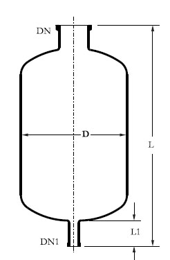
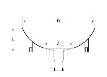
Cylindrical Flask
| Nominal Cap. Ltr. | D mm | DN mm | DN1 mm | DN2 | Lmm | CAT. REF. |
|---|---|---|---|---|---|---|
| 5L | 200 | 50 | 25 | 40 | 475 | VCY5 |
| 10 L | 220 | 50 | 25 | 40 | 600 | VCY10 |
| 20 L | 300 | 80 | 25 | 50 | 650 | VCY20 |
| 30 L | 300 | 80 | 25 | 50 | 790 | VCY30 |
| 50 L | 420 | 100 | 40 | 100 | 795 | VCY50 |
| 100 L | 470 | 150 | 40 | 100 | 1020 | VCY100 |
| 150 L | 470 | 150 | 40 | 100 | 1315 | VCY150 |
| 200 L | 600 | 225 | 40 | 100 | 1190 | VCY200 |
| 300 L | 600 | 225 | 40 | 100 | 1590 | VCY300 |
| 400 L | 600 | 300 | 40 | 100 | 1715 | VCY400 |
Tolerance ±as per given general data in the vessel chapter.
Aspirator Bottle
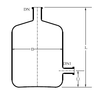
| Nominal Cap. Ltr. | D mm | DN mm | DN1 mm | DN2 | Lmm | CAT. REF. |
|---|---|---|---|---|---|---|
| 10 L | 215 | 40 | 25 | 410 | 100 | B10 |
| 20 L | 280 | 40 | 25 | 485 | 100 | B20 |
JACKETED VESSEL
For special applications, cylindrical vessels can be supplied with a jacket for heating or cooling. Jacket is sealed to the vessel with silicon rubber or viton '0' ring and other sealing compositions. The seal prevents impermissible high stresses between vessel and jacket and allows the movement which comes due to thermal expansion.
| Nominal Cap. Ltr. | DN mm | DN1 mm | DN2 mm | D MM | L mm | L1 mm | CAT. REF. |
|---|---|---|---|---|---|---|---|
| 5L | 100 | 25 | 25 | 165 | 825 | 150 | VZD5/4 |
| 150 | 50 | 25 | 40 | 600 | 150 | VZD5/6 | |
| 10 L | 150 | 80 | 25 | 50 | 650 | 150 | VZD10/6 |
| 225 | 80 | 25 | 50 | 790 | 175 | VZD10/9 | |
| 20 L | 225 | 100 | 40 | 100 | 795 | 200 | VZD20/9 |
| 300 | 150 | 40 | 100 | 1020 | 200 | VZD20/12 | |
| 30 L | 300 | 150 | 40 | 100 | 1315 | 200 | VZD30/12 |
| 50 L | 300 | 225 | 40 | 100 | 1190 | 200 | VZD50/12 |
| 60 L | 300 | 225 | 40 | 100 | 1590 | 200 | VZD60/12 |
| 100 L | 400 | 300 | 40 | 100 | 1715 | 210 | VZD100/16 |
| 450 | 300 | 40 | 100 | 1715 | 210 | VZD100/18 |
Tolerance ±as per given general data in the vessel chapter.
This vessel can also be supplied with metal jacket. Metal Jacket can be used in a maximum operating pressure of 2.0 bar g and a maximum operation temperature of 150OC.
Vessel Holder
Vessel holders is made of cast aluminium with a plaster lining shape to fit the vessel . Vessel holder is fitted with 3 jacking bolts.
| Vessel holder size wise | D mm | d mm | L mm | CAT. REF. |
|---|---|---|---|---|
| 20 L | 325 | 230 | 100 | VSS20 |
| 30 L | 325 | 230 | 100 | VSS30 |
| 50 L | 390 | 230 | 100 | VSS50 |
| 100 L | 300 | 225 | 100 | VSS100 |
| 200 L | 400 | 300 | 215 | VSS200 |
DIP PIPE
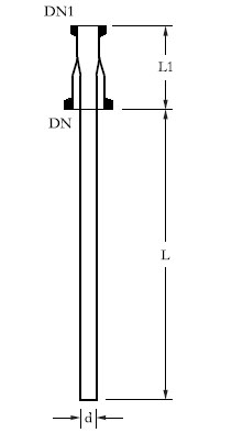
| Nominal Cap. Ltr | D mm | D1 mm | d mm | L mm | L1 mm | CAT. REF. |
|---|---|---|---|---|---|---|
| 20 L | 25 | 25 | 12 | 300 | 100 | DP20/1 |
| 50 L | 40 | 25 | 19 | 400 | 100 | DP50/1.5 |
| 100 L | 40 | 25 | 19 | 500 | 100 | DP100/1.5 |
| 200 L | 40 | 25 | 19 | 600 | 100 | DP200/1.5 |
SHORT DIP PIPE
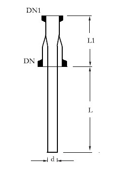
SHORT DIP PIPE Short dip pipe is used as re–entry tube for vessel, heat exchanger etc.
| Nominal Cap. Ltr | D mm | D1 mm | d mm | L mm | L1 mm | CAT. REF. |
|---|---|---|---|---|---|---|
| 20 L | 25 | 25 | 12 | 300 | 100 | DP20/1 |
| 50 L | 40 | 25 | 19 | 400 | 100 | DP50/1.5 |
| 100 L | 40 | 25 | 19 | 500 | 100 | DP100/1.5 |
| 200 L | 40 | 25 | 19 | 600 | 100 | DP200/1.5 |
GAS SPARGER
Gas sparger is used for gas feeding & sparging in vessels.
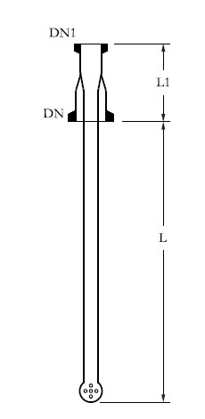
| Nominal Cap. Ltr | DN mm | DN1 mm | d mm | L mm | L1 mm | No. of Holes | CAT. REF. |
|---|---|---|---|---|---|---|---|
| 20 L | 25 | 25 | 12 | 300 | 100 | 5 x 1mm | GS20/1 |
| 50 L | 40 | 25 | 19 | 400 | 100 | 5 x 1mm | GS50/1.5 |
| 100 L | 40 | 25 | 19 | 500 | 100 | 5 x 1mm | GS100/1.5 |
| 200 L | 40 | 25 | 19 | 600 | 100 | 5 x 1mm | GS200/1.5 |
Thermometer Pocket
Thermometer pocket is used to put thermometer , where temperature need
to be measured.
| Nominal Cap. Ltr. | DN mm | d mm | L mm | L1 mm | CAT. REF. |
|---|---|---|---|---|---|
| 5L | 25 | 12 | 150 | 50 | TP5/1 |
| 10 L | 25 | 12 | 200 | 50 | TP10/1 |
| 20 L | 25 | 12 | 300 | 50 | TP20/1 |
| 50 L | 40 | 19 | 400 | 50 | TP50/1.5 |
| 100 L | 40 | 19 | 500 | 50 | TP100/1.5 |
| 200 L | 40 | 19 | 600 | 50 | TP200/1.5 |
| 300 L | 40 | 19 | 680 | 50 | TP300/1.5 |
Stirrers
A variety of stirrers and stirrer drives are available to use glass vessel as agitated reaction equipments. Stirrer assemblies are used with spherical or cylindrical vessels and generally comprise two main components: a drive unit (including shaft seal) and a stirrer shaft. In addition a reducer or vessels cover is normally required, to connect the top neck of the vessel to the drive unit. Variable speed drive unit can be supplied on request.
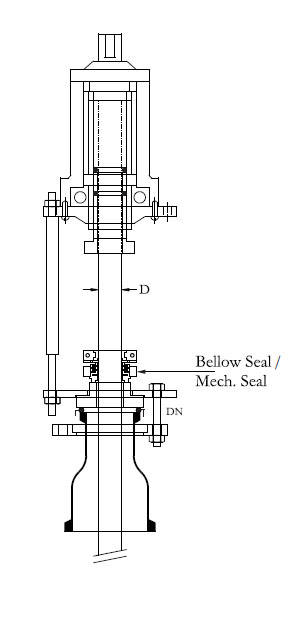
Chuck & Seal Assembly
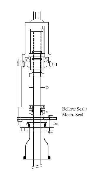
This unit is suitable for use under corrosive conditions. Only GLASS & PTFE are exposed to process fluids. Bellow seal can be used under vacuum down to 10mm Hg absolute. Mechanical seal can be used under vacuum1 mm Hg absolute or under pressure permitted into glass vessels.
| Vessel Cap. Ltr. | DN mm | D mm | CAT. REF. BELLOW SEAL | CAT. REF. MECH. SEAL |
|---|---|---|---|---|
| 10 L | 50 | 24.5 | CSA1 | CSM1 |
| 20 L | 50 | 24.5 | CSA1 | CSM1 |
| 50 L | 50 | 24.5 | CSA1 | CSM1 |
| 100 L | 50 | 45.5 | CSA1.5 | CSM1.5 |
| 200 L | 50 | 45.5 | CSA1.5 | CSM1.5 |
| 300 L | 50 | 45.5 | CSA1.5 | CSM1.5 |
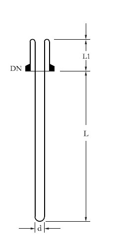
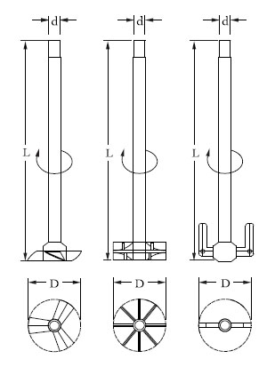
Glass Stirrer with Teflon Blade
This stirrer is used for low viscosity fluid.
| Vessel Cap. Ltr | d mm | D mm | L | L1 | L2 | CAT. REF. |
|---|---|---|---|---|---|---|
| 5L | 24.5 | 40 | 625 | 350 | 25 | STB5 |
| 10 L | 24.5 | 40 | 700 | 350 | 25 | STB10 |
| 20 L | 24.5 | 70 | 800 | 350 | 25 | STB20 |
| 50 L | 24.5 | 100 | 1000 | 350 | 25 | STB50 |
| 100 L | 45.5 | 150 | 1200 | 400 | 30 | STB100 |
| 200 L | 45.5 | 175 | 1400 | 400 | 30 | STB200 |
| 300 L | 45.5 | 200 | 1500 | 400 | 30 | STB300 |
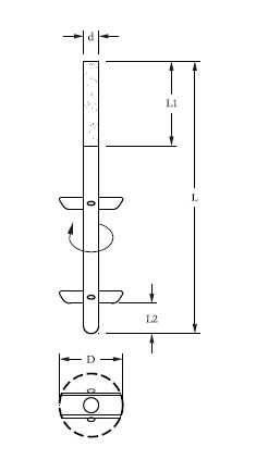
Vortex Stirrer
This stirrer is used for low viscosity fluid containing small solid particles.
| Vessel Cap. Ltr | d mm | D mm | L | L1 | L2 | CAT. REF. |
|---|---|---|---|---|---|---|
| 5L | 24.5 | 40 | 625 | 350 | 50 | STV5 |
| 10 L | 24.5 | 40 | 700 | 350 | 50 | STV10 |
| 20 L | 24.5 | 50 | 800 | 350 | 50 | STV20 |
| 50 L | 24.5 | 65 | 1000 | 350 | 65 | STV50 |
| 100 L | 24.5 | 65 | 1200 | 400 | 65 | STV100 |
| 200 L | 45.5 | 105 | 1400 | 400 | 65 | STV200 |
| 300 L | 45.5 | 105 | 1500 | 400 | 65 | STV300 |
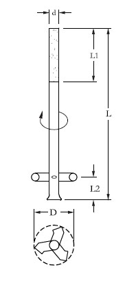
Propeller Stirrer
This stirrer is used for high viscosity fluid containing big solid particles.
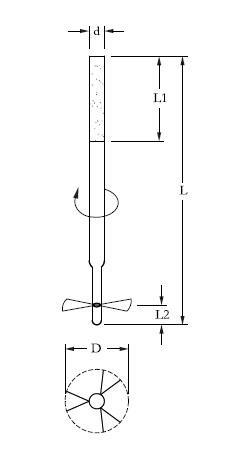
| Vessel Cap. Ltr | d mm | D mm | L | L1 | L2 | CAT. REF. |
|---|---|---|---|---|---|---|
| 5L | 24.5 | 40 | 625 | 350 | 50 | STP5 |
| 10 L | 24.5 | 40 | 700 | 350 | 50 | STP10 |
| 20 L | 24.5 | 50 | 800 | 350 | 50 | STP20 |
| 50 L | 24.5 | 65 | 1000 | 350 | 65 | STP50 |
| 100 L | 24.5 | 65 | 1200 | 400 | 65 | STP100 |
| 200 L | 45.5 | 105 | 1400 | 400 | 65 | STP200 |
| 300 L | 45.5 | 105 | 1500 | 400 | 65 | STP300 |
PTFE Stirrer
This stirrer produces axial primary flow with a radial component and is particularly suitable for homogenisation and suspension. It is also suitable for general stirring duties with simultaneous heat transfer (heating or cooling) between the liquid being stirred and the vessel wall. It can also be used for dispersion (including from gases) and emulsification. This stirrer is available in three combinations (like Propeller /Turbine/Anchor type).
| L | d | D | CAT. REF. |
|---|---|---|---|
| 700 | 45 | 150 | SPT150/700 |
| 800 | 45 | 150 | SPT150/800 |
| 1100 | 45 | 150 | SPT150/1100 |
| 1350 | 45 | 200 | SPT200/1350 |
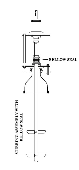
Stirring assembly with bellow seal
A stirrer is assembled in chuck with bellow seal and appropriate reducer. This assembly is
convenient to install on a vessel . This assembly mainly consists of :
A. Glass Stirrer
B. Chuck and seal.
C. Glass Reducer
STIRRER
| Vessel Cap. Ltr | Stripper Used | Chuck & Seal Used | Reducer Used | CAT. REF. |
|---|---|---|---|---|
| 10 L | STB10 | CSA1 | - | STBA10 |
| 20 L | STB20 | CSA1 | PR3/2 | STBA20 |
| 50 L | STB50 | CSA1 | PR4/2 | STBA50 |
| 100 L | STB100 | CSA1.5 | PR6/3 | STBA100 |
| 200 L | STB200 | CSA1.5 | PR9/3 | STBA200 |
| 300 L | STB300 | CSA1.5 | PR12/3 | STBA300 |
| 10 L | STV10 | CSA1 | - | STBA10 |
| 20 L | STV20 | CSA1 | PR3/2 | STBA20 |
| 50 L | STV50 | CSA1 | PR4/2 | STBA50 |
| 100 L | STV100 | CSA1.5 | PR6/3 | STBA100 |
| 200 L | STV200 | CSA1.5 | PR9/3 | STBA200 |
| 300 L | STV300 | CSA1.5 | PR12/3 | STBA300 |
| 10 L | STP10 | CSA1 | - | STBA10 |
| 20 L | STP20 | CSA1 | PR3/2 | STBA20 |
| 50 L | STP50 | CSA1 | PR4/2 | STBA50 |
| 100 L | STP100 | CSA1.5 | PR6/3 | STBA100 |
| 200 L | STP200 | CSA1.5 | PR9/3 | STBA200 |
| 300 L | STP300 | CSA1.5 | PR12/3 | STBA300 |
Stirrer Assembly with mechanical seal
A stirrer is assembled in chuck with mechanical seal and appropriate reducer. This
assembly is convenient to install on a vessel.
The assembly consists of :
A. Glass Stirrer
B. Chuck and mechanical seal
C. Glass Reducer
Stirrer
| Vessel Cap. Ltr | Stripper Used | Chuck & Seal Used | Reducer Used | CAT. REF. |
|---|---|---|---|---|
| 10 L | STB10 | CSA1 | - | STBA10 |
| 20 L | STB20 | CSA1 | PR3/2 | STBA20 |
| 50 L | STB50 | CSA1 | PR4/2 | STBA50 |
| 100 L | STB100 | CSA1.5 | PR6/3 | STBA100 |
| 200 L | STB200 | CSA1.5 | PR9/3 | STBA200 |
| 300 L | STB300 | CSA1.5 | PR12/3 | STBA300 |
| 10 L | STV10 | CSA1 | - | STBA10 |
| 20 L | STV20 | CSA1 | PR3/2 | STBA20 |
| 50 L | STV50 | CSA1 | PR4/2 | STBA50 |
| 100 L | STV100 | CSA1.5 | PR6/3 | STBA100 |
| 200 L | STV200 | CSA1.5 | PR9/3 | STBA200 |
| 300 L | STV300 | CSA1.5 | PR12/3 | STBA300 |
| 10 L | STP10 | CSA1 | - | STBA10 |
| 20 L | STP20 | CSA1 | PR3/2 | STBA20 |
| 50 L | STP50 | CSA1 | PR4/2 | STBA50 |
| 100 L | STP100 | CSA1.5 | PR6/3 | STBA100 |
| 200 L | STP200 | CSA1.5 | PR9/3 | STBA200 |
| 300 L | STP300 | CSA1.5 | PR12/3 | STBA300 |
Stirrer Drive Motor ( Non- Flame Proof)
A 1400 RPM 3 Phase non-flameproof motor with built-in gear is supplied along with a flexible shaft. A motor coupling to couple the flexible shaft to motor is also provided. Other end of the flexible shaft is to be fitted into the chuck.
.jpg)
| HP | SPEED RPM | CAT. REF. |
|---|---|---|
| 0.25 | 190 | RSD 0.25 |
| 0.5 | 195 | ARSD 0.5 |
| 1.0 | 195 | RSD 1 |
This motor is also available in FLAME PROOF
Speed Variator ( Drive )
3 Phase non-flame proof regulators are available to control the speed of stirrer drives.
.jpg)
| Type | Phase | CAT. REF. |
|---|---|---|
| 0.25 | 190 | FSD0.25 |
| 0.5 | 195 | FSD0.5 |
| 1.0 | 195 | FSD1 |
Baths
M. S. Heating bath is used for electrical or steam heating of glass vessels. Depending upon the temperature requirements, different types of thermic fluids oil or water can be used as heating media. Heating bath is provided with a pair of NON flame proof heaters with digital controller box, M.S coil for passing the steam or cooling water, cushioned vessel holding ring, a bottom outlet sealing arrangement, a lid and threaded socket type inlets and outlets.
| Vessel Cap. Ltr | D mm | L mm | POWER (kW) | CAT. REF. |
|---|---|---|---|---|
| 5L | 325 | 225 | 2 kW ( 2 x 1000) | BH5 |
| 10 L | 350 | 250 | 2 kW ( 2 x 1000) | BH10 |
| 20 L | 480 | 340 | 3 kW ( 3 x 1500) | BH20 |
| 50 L | 615 | 415 | 4 kW ( 2 x 2000) | BH50 |
| 100 L | 720 | 535 | 6 kW ( 2 x 3000) | BH100 |
| 200 L | 900 | 620 | 8 kW ( 2 x 4000) | BH200 |
* S.S. Heating bath can be supplied on request . This should be specified during inquiry stage.
* S.S. / Copper coil can be supplied on request . This should be specified during inquiry stage.
Heating Bath Jacketed with Coil & Heater
M.S. Jacketed Heating bath is provided with a coil inside to circulate either steam or heat transfer fluid depending upon the application . Provision for placing a electrical heater is also kept .
(Non Flame proof )- Heater can also be provided along with the bath on request . Although the standard heating bath is specifically designed for spherical vessel , similar bath for cylindrical vessel can also be supplied on special order. This heating bath can be fitted with suitable temperature control equipments if required.
| Vessel Cap. Ltr | D mm | D1 mm | L mm | POWER (kW) | CAT. REF. |
|---|---|---|---|---|---|
| 5L | 395 | 325 | 260 | 2 kW ( 2 x 1000) | BHD5 |
| 10 L | 420 | 350 | 285 | 2 kW ( 2 x 1000) | BHD10 |
| 20 L | 550 | 480 | 360 | 3 kW ( 3 x 1500) | BHD20 |
| 50 L | 685 | 615 | 465 | 4 kW ( 2 x 2000) | BHD50 |
| 100 L | 830 | 720 | 560 | 6 kW ( 2 x 3000) | BHD100 |
| 200 L | 1050 | 900 | 680 | 8 kW ( 2 x 4000) | BHD200 |
* S.S. Heating bath can be supplied on request . This should be specified during inquiry stage.
* S.S. / Copper coil can be supplied on request . This should be specified during inquiry stage.
Cooling Bath
Cooling bath is used for cooling the glass vessel with ice crystals. Cooling bath is provided with cushioned vessel holding ring, a bottom outlet sealing arrangement and a lid.
| Vessel Cap. Ltr | D mm | L mm | POWER (kW) | CAT. REF. |
|---|---|---|---|---|
| 5L | 325 | 225 | 2 kW ( 2 x 1000) | BHC5 |
| 10 L | 350 | 250 | 2 kW ( 2 x 1000) | BHC10 |
| 20 L | 480 | 330 | 3 kW ( 3 x 1500) | BHC20 |
| 50 L | 615 | 415 | 4 kW ( 2 x 2000) | BHC50 |
| 100 L | 720 | 535 | 6 kW ( 2 x 3000) | BHC100 |
| 200 L | 900 | 620 | 8 kW ( 2 x 4000) | BHC200 |
Heating Mantle
As an alternative to heating bath, electric heating mantle can also be supplied for spherical & cylindrical vessels. It’s heating power varies according to the nominal capacity of the vessel involved.
This heating mantle is sub-divided into several heating zones each of which is equipped with a temperature probe so that the surface temperature of the vessel can be monitored. This work in conjunction with the control unit includes in the supply to prevent local hot spots occurring. The control unit also includes energy regulators , which can be used to control the heat input separately for each heating zone depending on the liquid level.
| Vessel Cap. Ltr | D mm | L mm | ELEC. SUPPLY | CIRCUTS | POWER (kW) | CAT. REF. |
|---|---|---|---|---|---|---|
| 5L | - | 260 | 230V | 1 | 0.6 kW ( 1 x 600) | JMD5 |
| 10 L | - | 285 | 230V | 3 | 1.0 kW ( 2 x 500) | JMD10 |
| 20 L | 550 | 365 | 230V | 3 | 1.5 kW ( 3 x 500) | JMD20 |
| 50 L | 685 | 465 | 440V | 3 | 3.6 kW ( 4 x 900) | JMD50 |
| 100 L | 830 | 560 | 440V | 3 | 5.4 kW ( 6 x 900) | JMD100 |
| 200 L | 1050 | 680 | 440V | 6 | 8.0 kW ( 8 x 1000) | JMD200 |
Measurement & control
This instrument is mainly used to monitor the temperature of liquid in a glass vessel in a typical
glass distillation unit.
This instrument consists of a Temperature indicator and a Resistance Temperature Detector
(RTD). The instrument works on 230V, 50Hz power supply. This displays the temperature in
degree Centigrade in three and half digits of 12.5mm character height.
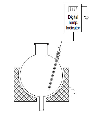
| Vessel Cap. Ltr | RTD LENGTH |
CAT. REF. |
|---|---|---|
| 20 | 400 | DTI20 |
| 50 | 500 | DTI50 |
| 100 | 600 | DTI100 |
| 200 | 700 | DTI200 |
Two Point Digital Temperature Indicator
This instrument is mainly used to monitor the temperature of liquid in a glass vessel and temperature of vapours at reflux divider in a typical glass distillation unit. This instrument consists of a Temperature indicator and two Resistance temperature detectors (RTDs). The instrument works on 230V, 50Hz power supply.
This displays the temperature in degree Centigrade in three and half digits of 12.5mm character height. A switch is provided to see the two temperatures alternatively.
| Vessel Cap. Ltr | RTD LENGTH FOR VESSEL | RTD LENGTH FOR REFLUX DIVIDER |
CAT. REF. |
|---|---|---|---|
| 20 | 400 | 200 | DTT20 |
| 50 | 500 | 225 | DTT50 |
| 100 | 600 | 250 | ADTT100 |
| 200 | 700 | 300 | ADTT200 |
Continuous Temperature Controller
This instrument displays and controls the temperature continuously by switching the power supply ON and OFF in an electrical heating equipment as per the initial settings of heating temperature, band width and reset temperature. The instrument consists of a Temperature controller, a series magnetic controller and a Resistance Temperature Detector (RTD).
RTD is put into the Thermometer Pocket of the glass vessel and desired settings are done. As the temperature in the vessel reaches to the set heating temperature, the temperature controller cuts the power in heating the equipment . Power starts on again as the temperature goes down as per the settings of band width and reset temperature.
This instrument works on power supply of 230V 50Hz and can be used with heating mantles and heating baths of all the size. It displays the temperature in Degree Centigrade (°C).
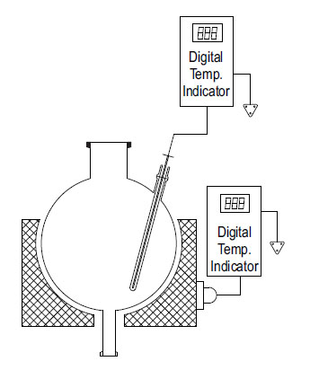
| Vessel Cap. Ltr | RTD LENGTH | CAT. REF. |
|---|---|---|
| 20 | 400 | CTC20 |
| 50 | 500 | CTC50 |
| 100 | 600 | CTC100 |
| 200 | 700 | CTC200 |
Decantor (separator)
Decantation is a process of separation of two immiscible liquids, having different densities. When these liquids are allowed to settle, two distinct layers are formed, heavier at bottom and lighter at top. This is a decantor which is suitable for continuous decantation .The mixture of liquids is continuously feed in the decantor at low velocity. This allows sufficient residence time for the formation of separate layers. The light phase liquid is continuously removed from the light phase outlet at the top. The heavy phase liquid enters the dip pipe at lower and overflow in the discharge pipe and is removed from the bottom.
This decantor provides continuous separation, visual monitoring, and ensures separation even after feeding is stopped. Decantor can be provided with adjustable overflow valve, (Type B) to adjust the position of interface for different operating situations
.jpg)
 - b.jpg)
 last.jpg)
| Nom. Cap. | DN | DN1 | DN2 | DN3 | DN4 | DN5 | DN6 | DN7 | L | L1 | L2 | L3 | L4 | Type | CAT. REF. |
|---|---|---|---|---|---|---|---|---|---|---|---|---|---|---|---|
| 20 | 80 | 25 | 50 | 25 | 25 | 25 | 25 | 50 | 800 | 125 | 525 | 150 | - | A | SPS20 |
| 50 | 100 | 40 | 50 | 25 | 25 | 40 | 40 | 50 | 1025 | 150 | 725 | 150 | - | A | SPS50 |
| 100 | 150 | 40 | 50 | 25 | 25 | 40 | 40 | 50 | 1175 | 200 | 825 | 150 | - | A | SPS100 |
| 200 | 225 | 40 | 50 | 25 | 25 | 40 | 40 | 50 | 1475 | 250 | 1075 | 150 | - | A | SPS200 |
| 20 | 80 | 25 | 50 | 25 | 25 | 25 | 25 | 50 | 1000 | 125 | 525 | 150 | 200 | B | SPA20 |
| 50 | 100 | 40 | 50 | 25 | 25 | 40 | 40 | 50 | 1225 | 150 | 725 | 150 | 200 | B | SPA50 |
| 100 | 150 | 40 | 50 | 25 | 25 | 40 | 40 | 50 | 1375 | 200 | 825 | 150 | 200 | B | SPA100 |
| 200 | 225 | 40 | 50 | 25 | 25 | 40 | 40 | 50 | 1675 | 250 | 1075 | 150 | 200 | B | SPA200 |
Decantor can be constructed with horizontal cylindrical vessels and to provide larger separating surface (Mention catalouge ref. is AHPA & AHPS).
Reflux Reaction Cum Distillation Unit
This is a versatile unit and can be used as Reaction Distillation Unit, Fractional Distillation Unit or a combination of both. All features of Reaction Distillation Unit and Fractional Distillation Unit are incorporated.
The units is available in vessel sizes of 20, 50, 100 & 200L, 300L and is suitable for operation under atmospheric pressure and full vaccum.
| Reactor Bath Capacity | Bath KW | Addition Vessel Size | Vapour Line | CONDENSER HTA (m2) | RO.COOLER HTA (m2) | Unit Cat. Ref. | Unit Cat. Ref. |
|---|---|---|---|---|---|---|---|
| 10 L | 2 | 2 L | 50 DN | 0.2 | 0.1 | 2 L, 2 L | RDU 10 |
| 20 L | 3.6 | 5 L | 80 DN | 0.35 | 0.1 | 5 L, 5 L | RDU 20 |
| 50 L | 4.5 | 5 L | 100 DN | 0.5 | 0.2 | 5 L, 5 L | RDU 50 |
| 100 L | 6 | 10 L | 150 DN | 1.5 | 0.35 | 10 L, 10 L | RDU 100 |
| 200 L | 8 | 20 L | 150 DN | 1.5 | 0.35 | 20 L, 20 L | RDU 200 |
| 300 L | 12 | 20 L | 225 DN | 2.5 | 0.5 | 20 L, 20 L | RDU 300 |
* These unit is also available in cylindrical vessel .
* Heating Mantel is also available in the same unit , please specify before the order.
Multi - Purpose R&d Unit
This unit is more versatile and cost effective, capable of working at atmospheric pressure or under full vacuum .
This unit is suitable of performing the boiling under reflux, stripping and continuous distillation, batch distillation, Interface separation, without chemical reaction. The unit can be modified as per the specification and requirement of the customer.
| Reactor Bath Capacity | Bath KW | Addition Vessel Size | Vapour Line | CONDENSER HTA (m2) | RO.COOLER HTA (m2) | Unit Cat. Ref. | Unit Cat. Ref. |
|---|---|---|---|---|---|---|---|
| 10 L | 2 | 2 L | 50 DN | 0.2 | 0.1 | 2 L, 2 L | MRD 10 |
| 20 L | 3.6 | 5 L | 80 DN | 0.35 | 0.1 | 5 L, 5 L | MRD 20 |
| 50 L | 4.5 | 5 L | 100 DN | 0.5 | 0.2 | 5 L, 5 L | MRD 50 |
| 100 L | 6 | 10 L | 150 DN | 1.5 | 0.35 | 10 L, 10 L | MRD 100 |
* These unit is also available in cylindrical vessel .
* Heating Mantel is also available in the same unit , please specify before the order.
Mobile Vessel
Mobile Vessel is perfect for pilot plant and production use to transport and store products. Cylindrical Mobile Vessel can be supplied from 30 to 200 liter and spherical vessels from 50 to 200 liter. If required, it can also be graduated.
| NOMINAL CAPACITY LTR | DN | DN 1 | L | CONDENSER HTA (m2) | CAT. REF. with PUMP |
|---|---|---|---|---|---|
| 30 | 300 | 40 | 1500 | MCV30 | MCV30/P |
| 50 | 300 | 40 | 1700 | MCV50 | MCV50/P |
| 100 | 450 | 50 | 1950 | MCV100 | MCV100/P |
| 150 | 450 | 50 | 2250 | MCV150 | MCV150/P |
| 200 | 450 | 50 | 2550 | MCV200 | MCV200/P |
NOTE : "L" is Vary ±50mm or as require size in special case. Mobile Vessel is also available in Spherical vessel .
Jacketed Cylindrical Mixing Reactor
| Reactor Capacity | Jacketed Mixing Reactor Cat. Ref. |
|---|---|
| 5 L | JMR 5 |
| 10 L | JMR 10 |
| 20 L | JMR 20 |
| 30 L | JMR 30 |
| 50 L | JMR 50 |
Mixing Reactor
Mixing Reactor systems represent a long-term evaluation of equipment and customer requirements. The Mixing Reactors are preferably used for wide applications in laboratory, pilot plant & for small-scale production. They reduce the need for investment in permanent installations & also reduce the pressure & temperature losses resulting from pipeline installations. These reactors are available with spherical shape & cylindrical shape. These reactors are also available in cylindrical jacketed form.
Construction of assembly :
SPHERICAL & Cylindrical Mixing Reactor
| Reactor Capacity | Spherical Cat. Ref. | Cylindrical Cat. Ref. |
|---|---|---|
| 20 L | SMR 20 | CMR 20 |
| 50 L | SMR 50 | CMR 50 |
| 100 L | SMR 100 | CMR 100 |
| 200 L | SMR 200 | CMR 200 |
| 300 L | SMR 300 | CMR 300 |
STORAGE TANK OF VOLUME 100–500
They are composed of glass cylindrical kettles or flasks of capacity200-500, discharges of vessels are consistent by glass piping DN 50/40.
Cylindrical Vessel
| NOMINAL CAPACITY LTR | D MM |
L MM | CAT. REF. |
|---|---|---|---|
| 100 L | 470 | 1020 | SCY100 |
| 150 L | 470 | 1315 | SCY150 |
| 200 L | 600 | 1190 | SCY200 |
| 300 L | 600 | 1590 | SCY300 |
| 400 L | 600 | 1715 | SCY400 |
| 500 L | 760 | 1550 | SCY500 |
Liquid-liquid Extraction Unit
Liquid extraction, sometimes called solvent extraction, is the separation of constituents of a liquid solution by contact with another insoluble liquid. The unit described here is for a semi-batch operation.
The liquid to be extracted is poured into an extraction vessel. Solvent is boiled in a reboiler vessel and condensed in an overhead condenser, the condensed liquid collected in a reflux divider and passed through pipework to the extraction vessel. The pipework incorporates valves in order that the solvent can enter the extraction vessel at either the base of the top, depending on the relative densities of the solvent and liquid to be extracted. The solvent and the extracted liquid pass back to the reboiler and the process is repeated until the extraction is complete. The extraction vessel is then drained and the solvent evaporated from the reboiler vessel and collected in the extraction vessel enables the two liquids to be drained form their respective vessels.
The unit is available in vessel sizes of 10, 20, & 50L and is suitable for operation under atmoshepric pressure.
| REACTOR CAPACITY | BATH KW | VAPOUR LINE | EXTRACTION VESSEL | CONDENSER M2 | UNIT CAT. REF. |
|---|---|---|---|---|---|
| 10 L | 3 | 40mmx1m | 10 L | 0.35 | LLU 10 |
| 20 L | 4.5 | 50mmx1m | 20 L | 0.5 | LLU 20 |
| 50 L | 6 | 80mmx1m | 50 L | 1.5 | LLU 50 |
Solid Liquid Extraction Unit
This operation involves preferential solublising of one or more soluble constituents (solutes) of a solid mixture by a liquid solvent. The unit described here is for a semi-batch operation.
The solid to be extracted is put inside a glass fiber bag and placed in an extraction vessel. Solvent from the reboiler is continuously evaporated,condensed and circulated through a reflux divider by means of piping network and valves. When desired/ steady concentration of solute is achieved in the solution the operation is discontinued. The solution is drained off and collected for further use.
After charging fresh solid in fiber bag and solvent in reboiler, the cycle can be restarted again.The unit is available in vessel sizes of 10, 20, & 50L and is suitable for operation under atmospheric pressure.
| REACTOR CAPACITY | BATH KW | VAPOUR LINE | EXTRACTION VESSEL | CONDENSER M2 | UNIT CAT. REF. |
|---|---|---|---|---|---|
| 10 L | 3 | 40mmx1m | 10 L | 0.35 | SLU 10 |
| 20 L | 4.5 | 50mmx1m | 20 L | 0.5 | SLU 20 |
| 50 L | 6 | 80mmx1m | 50 L | 1.5 | SLU 50 |
Assemblies Over Glass Lined Reactor
Glass Lined Reactors are used instead of glass reactors specially when scale of operation is large and relatively high pressure steam is to be used as heating media. Quite often assemblies like Simple Distillation Unit, Reaction Distillation Unit, Fractional Distillation Unit etc. are installed above glass lined reactors. The basic features of these assemblies remain the same but glass shell and tube heat exchanger is preferred due to large scale of operation. A typical fractional distillation unittype assembly over GLR is shown in nearby figure. The assemby can be separated into different categories.
Hcl Gas Generation - Azeotropic Boiling Route
Commercial hydrochloric acid is available in the market as 30% aqueous solution and is widely used in industry in large quantities. But for certain applications e.g. in bulk drug/pharmaceutical industry HCl gas is required in gaseous form. Such users generate anhydrous HCl from commercial grade for their captive consumption. Several methods have been adopted and generation through BOILING ROUTE is also a reliable technique. Salient features :
RAW MATERIAL & UTILITY REQUIREMENTS. :
The indicative requirements for 20kg/hr HCl gas generator are given below:
HCI Gas Generator
(Sulphuric Acid Route).
Commercial hydrochloric acid is available in the market as 30% aqueous solution and is widely used in industry in large quantities. But for certain applications e.g. in bulk drug/pharmaceutical industry HCI gas is required in anhydrous state for critical reactions where moisture cannot be tolerated. Such users generate anhydrous HCI from commercial grade for their captive consumption. Several methods have been adopted but generation through SULPHURIC ACID ROUTE is the most reliable and handy technique. Salient Features :
Raw Material Requirement
The indicative requirements for 20 kg/hr HCI gas generator are given below:
Hcl GAS ABSORBER - ADIABATIC TYPE
HCL absorption columns are used for absorption of Hydrochloric gas which statutorily are not permitted to vent into the atmosphere, and to produce the HCl acid. Hydrogen Chloride is very soluble in water but it's absorption is complicated by the high heat of solution and the high partial pressure over warm concentrated solutions. In practice, the basic problem in making concentrated solutions is one of efficient heat removal. In this type of absorber, the heat of absorption is removed by evaporation of water and acid in the column. The vapour being condensed is diluted with 'makeup' therefore, mostly removed via condenser. Concentration and cooling of the liquid phase is assisted by evaporation of water to maintain the vapour/liquid equilibrium in the lower part of the packed section. The column is constructed with a series of packed sections, a gas introduction point below that, a condenser on the top, and a cooler at the bottom and water is sprayed from the top and acid is collected from the bottom. Hcl absorption columns are available in 80DN to 300DN diameter (for the gas rate 10 Kgs/hr to 300 Kgs/hr approx.)
| PACKED COLUMN | CONDENSER HTA (m2) | GAS RATE (Approx.) | EXTRACTION VESSEL | CAT. REF. |
|---|---|---|---|---|
| 80mmx3m | 0.35m2x2 | 40mmx1m | 10 Kg/hr | HCL3 |
| 100mmx4m | 0.5m2x2 | 50mmx1m | 20 Kg/hr | HCL4 |
| 150mmx4m | 1.5m2x2 | 80mmx1m | 60 Kg/hr | HCL6 |
| 225mmx4.5m | 2.5m2x2 | 80mmx1m | 150 Kg/hr | HCL9 |
| 300mmx4.5m | 2.5m2x2 | 80mmx1m | 300 Kg/hr | HCL12 |
GAS ABSORBER - FALLING FILM TYPE
Process Description
Efficient gas absorption depends on the following: 1. Intimate contact 2. Efficient Heat Transfer This is achieved in a Falling Film Absorber which is essentially a shell & tube heat exchanger in which both, gas to be absorbed and absorbing liquid, flows co-currently downward with extraction of heat by circulation of coolant in the shell. The abssorbing liquid is circulated through a tank till desired concentration is achieved. The liquid flows at such a rate that the tubes do not flow full of the liquid but instead, descends by gravity along the inner walls of the tubes as a thin film. Obviously, this produces a much greater linear velocity for a given rate flow than could be obtained if the tube flowed full. The equipment works as a number of water cooled-wall columns in parallel and each tube is provided with distribution system on top to effect uniform distribution of both liquid and gas and also formation of a thin liquid film on the inner surface of the tube.
SALIENT FEATURES
Other Area Of Application:
SPECIFICATIONS:
| NOMINAL SIZE (mm) | ABSORBER AREA (m2) | NO. OF TUBE TUBE OD (mm) | MAX. GAS ABSORPTION RATE ( Pure HCL) ( kg/Hr) | MAX. ACID PROD. RATE (As 30% CL )(kg/Hr) |
MAX. ACID PROD. RATE (As 30% CL )(kg/Hr) |
|---|---|---|---|---|---|
| 80 | 1.00 | 4/20 | 30 | 100 | FFA3 |
| 100 | 1.76 | 7/20 | 60 | 200 | FFA4 |
| 150 | 4.80 | 19/20 | 150 | 500 | FFA6 |
| 225 | 7.80 | 31/20 | 250 | 833 | FFA9 |
| 300 | 15.30 | 61/20 | 500 | 1667 | FFA12 |
| 400 | 36.00 | 143/20 | 1175 | 3917 | FFA16 |
| 450 | 47.00 | 187/20 | 1500 | 5000 | FFA18 |
| 600 | 84.00 | 333/20 | 2700 | 9000 | FFA24 |
BROMINE RECOVERY PLANT
Process Description
The feed is acidified with 30% HCl acid and acidified feed is fed to the scrubber by pump to scrub uncondensed chlorine from vent condenser and return back to the reaction column. In some cases the part feed is preheated using effluent from the reaction column prior to the entry of reaction column and part feed is fed to the scrubber to conserve energy.
Chlorine and Steam are also fed to the reaction column.
In the reaction column the feed is reacted with chlorine gas & bromine is liberated instantly. This liberated bromine is stripped out of the solution by live steam. The bromine and water vapor stream leaves the top of the column and enters the condenser . Condensate falls into the Phase Separator where it forms two phases, the light aqueous phase (water) being returned to the column ,while the heavy phase(Bromine) being feed the purification column. Cooling Water & Chilled Water is used as cooling media in heat exchanger provided at the top of the column to condense water vapor& Bromine.
Purification of the Bromine is achieved by distillation. Heat being introduced into the column through the reboiler. Bromine and Chlorine vapor leave the top of the column and enter the condenser .The Bromine gets condensed in the condenser and falls back into the column while uncondensed Chlorine vapor along with traces of Bromine escapes from the condenser and enter into the vent condenser, where remaining Bromine gets condensed and back to the crude Bromine receiver.
Pure Bromine is cooled in a product cooler to and goes to product receiver. Guard condenser is also provided at the top of the receiver to prevent escape of Bromine. Bromine is then collected in glass bottles. From Industrial Effluents (NaBr/KBr/HBr) From Sea -Bittern . Available up to 600 mm Dia. Over view of the system The system consists of :
Raw Material Requirement :
Products Specifications
Bromine Liquid : 99.7% (w/w, min)Chlorine : 0.3 % (w/w, max)
Non -volatile matter : Balance
SULPHURIC ACID DILUTION PLANT
Process Description
The unit consists of a Dilution Chamber, followed by a Heat Exchanger. Dilution Chamber is used for diluting concentrated Sulphuric acid to the desired concentration and the Heat Exchanger is used for bringing down the temperature of dilute acid to desired temperature, (when the concentrated acid mixes with water, large amounts of heat are released). The Heat Exchanger is of Shell and Tube type to dilute the acid. The acid should be added slowly to cold water to limit the buildup of heat. If water is added to the concentrated acid, enough heat can be released at once to boil the water and separate the acid. Sulfuric acid reacts with water to form hydrates with distinct properties.
The system consists of:
Outstanding Features
Valves
Introduction
Valves are widely used in the chemicals, pharmaceutical and allied industries. They form an essential part of any process plant or system in a wide range of applications, such as flow
controls, pressure relief and filtering.
Valve bodies are made-up of Borosilicate glass 3.3 with PTFE bellow. So the material comes into contact with these products (Borosilicate glass and PTEF) only. Therefore valves are fully
corrosion resistant and chemically inert as they have a glass body. Monitoring of the valve peration can be done visually. The entire valve range is suitable to use at full vacuum.
Line Valve
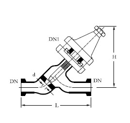
| DN |
DN1 |
d | L | H | CAT. REF. |
|---|---|---|---|---|---|
| 15 | 15 | 12 | 125 | 90 | PV07 |
| 25 | 25 | 18 | 175 | 175 | PV1 |
| 40 | 25 | 18 | 225 | 175 | PV1.5/1 |
| 40 | 40 | 26 | 225 | 200 | PV1.5 |
| 50 | 50 | 38 | 300 | 220 | PV2 |
Spindles are made of PTFE.
Drain Valve

| DN |
DN1 |
d | L | H | D | CAT. REF. |
|---|---|---|---|---|---|---|
| 15 | 15 | 12 | 125 | 90 | 14 | PVD07 |
| 25 | 25 | 18 | 175 | 175 | 28 | PVD1 |
| 40 | 25 | 18 | 225 | 175 | 28 | PVD1.5/1 |
| 40 | 40 | 26 | 225 | 200 | 42 | PVD1.5 |
| 50 | 50 | 38 | 300 | 220 | 50 | PVD2 |
Spindles are made of PTFE.
Angle Valve
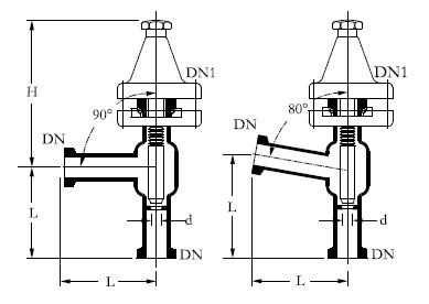
| DN |
DN1 |
d | L | H | degº | CAT. REF. |
|---|---|---|---|---|---|---|
| 15 | 15 | 12 | 50 | 80 | 90 | PVE07/90 |
| 15 | 15 | 12 | 50 | 80 | 80 | PVE07/80 |
| 25 | 25 | 18 | 100 | 175 | 90 | PVE1/90 |
| 25 | 25 | 18 | 100 | 175 | 80 | PVE1/80 |
| 40 | 40 | 26 | 150 | 200 | 90 | PVE1.5/90 |
| 50 | 50 | 38 | 150 | 220 | 90 | PVE2/90 |
Vent Valve
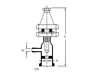
| DN |
D |
d | L | CAT. REF. |
|---|---|---|---|---|
| 15 | 11 | 10 | 125 | PVL07 |
| 25 | 11 | 10 | 150 | PVL1 |
| 40 | 11 | 10 | 150 | PVL1.5 |
pindles are made of PTFE.
Vent Vacuum Valve
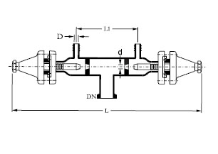
| DN |
D |
d | L | L1 | CAT. REF. |
|---|---|---|---|---|---|
| 25 | 12 | 10 | 280 | 85 | PVW1/07 |
| 40 | 12 | 10 | 280 | 85 | PVW1.5/07 |
pindles are made of PTFE.
NON-RETURN BALL TYPE Valve
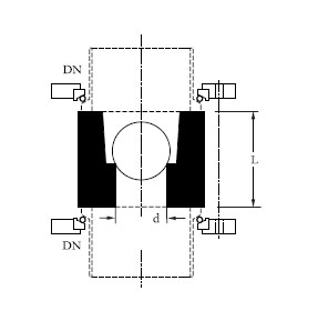
This valve is used in vertical lines only. It is clamped between buttress end using long bolts.
Total assembly consists of PTFE & glass ball.
| DN |
d | L | L1 | CAT. REF. |
|---|---|---|---|---|
| 15 | 5 | 19 | 85 | NRD07 |
| 25 | 10 | 25 | 85 | NRD1 |
| 40 | 15 | 33 | 85 | NRD1.5 |
BOTTOM OUTLET VALVE
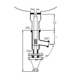
This valve is used in vertical lines only. It is clamped between buttress end using long bolts.
Total assembly consists of PTFE & glass ball.
| DN | DN1 | DN2 | d | L | L1 | L2 | CAT. REF. |
|---|---|---|---|---|---|---|---|
| 40 | 25 | 25 | 26 | 260 | 105 | 190 | BAL1.5 |
| 50 | 40 | 25 | 38 | 260 | 105 | 190 | BAL2 |
Adjustable Overflow Valve
This valve is suggested for adjusting the interface in separators (e.g. in Liquid to Liquid
Extraction). Level adjustment is substantially variable and is by means of a PTFE tube fitted
with sealing mouth that can be moved up and down inside a precision bore glass tube.
| DN | DN1 | d | L | L1 | L2 | CAT. REF. |
|---|---|---|---|---|---|---|
| 25 | 25 | 25 | 420 | 100 | 50 | OF1 |
| 40 | 25 | 25 | 600 | 150 | 90 | OF1.5 |
| 50 | 25 | 25 | 600 | 150 | 90 | OF2 |